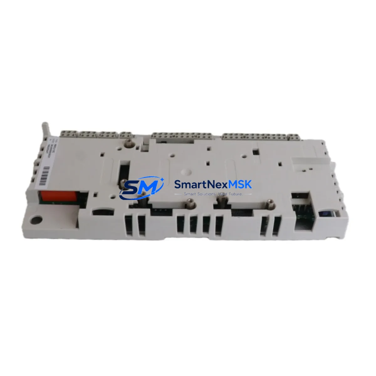
ABB RDCU-12 3AUA0000036521 Retrofit-Ready Drive Control Unit for ACS800 Control Systems
The ABB RDCU-12 (part number 3AUA0000036521) is a drive control unit engineered for seamless integration into ACS800 series variable frequency drive systems. As legacy ACS800 installations age and original control boards become increasingly difficult to source, the RDCU-12 has become the preferred retrofit solution for maintenance engineers and system integrators managing aging automation infrastructure. Whether you are executing a planned upgrade, responding to an unplanned board failure, or modernizing a control cabinet to extend its operational life, the RDCU-12 delivers the compatibility, reliability, and documentation support required for a controlled, low-risk migration.
This unit is a direct functional replacement for the original RDCU-12C and RDCU-02C control boards found in ACS800 single drives, multidrive modules, and cabinet-built configurations. It retains the same DDCS fiber-optic communication architecture, enabling it to interface with existing RDCO-01, RDCO-02, and RDCO-03 communication option modules without requiring firmware re-engineering or communication topology changes. Engineers migrating from older ACS600 platforms to ACS800 will also find the RDCU-12 a critical bridge component, particularly when the downstream control logic and DDCS network topology are being preserved during the transition.
Upgrade Compatibility Table
| Parameter | Details |
|---|---|
| Compatible Drive Series | ABB ACS800 Single Drive, ACS800 Multidrive, ACS800 Cabinet |
| Replaces | RDCU-12C, RDCU-02C (direct functional replacement) |
| Communication Interface | DDCS fiber-optic (compatible with RDCO-01, RDCO-02, RDCO-03) |
| Backplane / Rack Interface | Standard ACS800 control section slot — no mechanical modification required |
| Firmware Compatibility | Supports existing ACS800 application macros; parameter backup recommended before swap |
| Power Supply Requirement | 24 VDC internal supply from ACS800 power section — no external PSU required |
| Terminal Wiring | Identical terminal layout to RDCU-12C; existing field wiring reusable |
| Module Address Setting | Node address configurable via DIP switch on board — verify against existing DDCS topology |
| HMI / Panel Compatibility | Compatible with CDP312R and ACS-CP-C control panels; existing panel screens remain valid |
| Installation Requirement | ESD precautions required; power section must be de-energized before installation |
| Warranty | 12 Months — covers manufacturing defects and functional failure under normal operating conditions |
| Retrofit Recommendation | Perform full parameter upload/download cycle using DriveWindow or DriveStudio before and after replacement |
Retrofit Planning for Existing Automation Systems
A successful RDCU-12 retrofit begins well before the physical board swap. The first step is a thorough audit of the existing ACS800 drive configuration. Using ABB DriveWindow Light or DriveStudio, engineers should perform a complete parameter backup from the existing control unit. This backup preserves all application macro settings, speed references, torque limits, fault history, and I/O assignments — data that would otherwise require manual re-entry and re-commissioning if lost during the swap.
Before removing the original board, verify the power supply capacity of the ACS800 power section. The RDCU-12 draws its 24 VDC logic supply from the drive’s internal SMPS (switch-mode power supply). In older ACS800 units where the APBU-44C or APBU-12C pulse encoder interface board is also installed, confirm that the combined current draw remains within the power section’s rated auxiliary output capacity. If the existing AINT-02C or AINT-12C inverter control interface boards are present in the same control section, their power consumption must also be factored into the load calculation.
Terminal wiring on the RDCU-12 follows the same physical layout as the RDCU-12C, meaning existing field wiring for digital inputs, analog inputs, relay outputs, and the DDCS fiber-optic connections can be transferred directly. However, it is strongly recommended to photograph and document all terminal connections before disconnection, particularly the DDCS fiber-optic routing between the RDCU-12 and any RDCO communication option modules or AIMA-01 adapter modules in the system.
For systems where the ACS800 communicates upstream with a PLC or DCS via a fieldbus adapter — such as the RPBA-01 PROFIBUS-DP adapter, RCAN-01 CANopen adapter, or RDNA-01 DeviceNet adapter — the communication link parameters stored in the RDCU-12 must be verified post-replacement. Node addresses, baud rates, and process data mapping must match the upstream controller’s configuration exactly. In Siemens S7 or Allen-Bradley ControlLogix environments where the ACS800 is mapped as a fieldbus slave, a mismatch in these parameters will cause the drive to appear offline to the PLC, triggering process alarms and potentially initiating an emergency stop sequence.
Where the ACS800 is part of a larger multidrive system sharing a common DC bus, the RDCU-12 node address must be set correctly via the onboard DIP switches before power-up. Incorrect node addressing in a DDCS ring topology can cause communication conflicts that affect all drives on the network, not just the replaced unit. Coordinate with the system’s DDCS master — typically an APC (Application Program Controller) or an external master controller — to confirm the correct node assignment before energizing the system.
Downtime Control During System Migration
Minimizing production downtime during an RDCU-12 replacement requires a structured pre-outage preparation protocol. The most effective approach is to pre-configure the replacement RDCU-12 offline before the maintenance window begins. Using DriveStudio or DriveWindow, load the parameter backup taken from the original unit into the new board while it is still on the bench. This eliminates the need for manual parameter entry during the live outage window and significantly reduces the risk of transcription errors under time pressure.
Where the process cannot tolerate a cold restart, consider staging the replacement during a scheduled low-production period rather than during peak operation. For ACS800 drives controlling critical process equipment — such as compressors, pumps, or conveyor systems — coordinate with the process control team to ensure that the upstream PLC or DCS has been placed in manual override mode before the drive is de-energized. This prevents the control system from interpreting the drive’s absence as a process fault and initiating an unplanned shutdown of adjacent equipment.
After physical installation, the commissioning sequence should follow ABB’s standard ACS800 startup checklist: verify DC bus discharge, confirm terminal wiring integrity, restore parameters from backup, verify DDCS communication link status, check I/O signal mapping against the original configuration, and perform a no-load test run before returning the drive to automatic control. If the system includes an ABB CDP312R or ACS-CP-C operator panel, verify that the panel’s parameter set matches the restored configuration before handing control back to the automation system. Document all commissioning steps and retain the parameter backup file as part of the equipment’s maintenance record.
Retrofit Support FAQ
Q1: Is the RDCU-12 (3AUA0000036521) a direct drop-in replacement for the RDCU-12C?
Yes. The RDCU-12 is functionally and mechanically compatible with the RDCU-12C and RDCU-02C. It fits the same control section slot in ACS800 single drives and multidrive modules, uses the same terminal layout, and supports the same DDCS fiber-optic communication interface. No hardware modification to the drive cabinet is required.
Q2: Do I need to re-enter all drive parameters after replacing the RDCU-12?
Not if you perform a parameter backup before the swap. Using DriveWindow Light or DriveStudio, export the full parameter set from the original board. After installing the RDCU-12, restore the backup via the same tool. Verify critical parameters — particularly speed references, torque limits, and fieldbus communication settings — before returning the drive to service.
Q3: Will my existing fieldbus communication (PROFIBUS, DeviceNet, CANopen) continue to work after the replacement?
Yes, provided the communication option module (RPBA-01, RDNA-01, RCAN-01, etc.) is retained and the communication parameters are correctly restored from the parameter backup. Verify node address, baud rate, and process data mapping against the upstream PLC or DCS configuration after replacement. A brief communication test in manual mode is recommended before returning to automatic control.
Q4: What does the 12-month warranty cover?
The 12-month warranty covers manufacturing defects and functional failure under normal operating conditions from the date of shipment. Units are tested prior to dispatch to verify core functionality. The warranty does not cover damage resulting from incorrect installation, overvoltage events, ESD damage, or operation outside the specified environmental and electrical ratings. Contact sales@smartnexmsk.com for warranty claims or technical support.
© 2026 SMARTNEXMSK. All rights reserved.
Original Source: https://smartnexmsk.com
Contact: sales@smartnexmsk.com | +86 18259474341


