ABB RDO86-16L Retrofit-Ready Relay Output for AC500 Control Systems
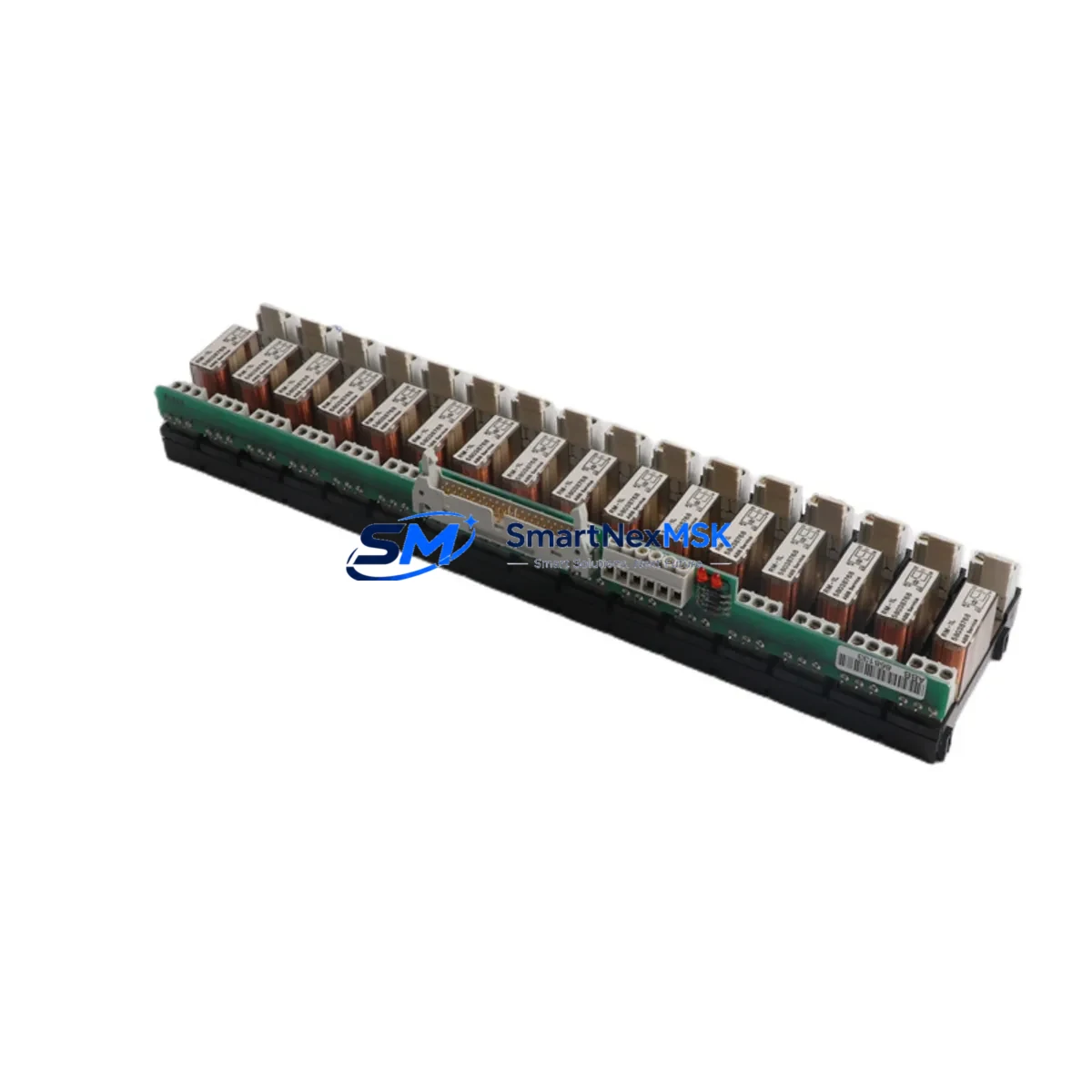
The ABB RDO86-16L is a 16-channel relay output module engineered for the ABB AC500 PLC platform, widely deployed in process automation, discrete manufacturing, building management, and utility control systems. As legacy AC500 installations age and original spare parts become increasingly difficult to source, the RDO86-16L has become a critical retrofit component for engineers tasked with modernizing aging control cabinets without full system replacement.
This module delivers reliable dry-contact relay switching across 16 independent output channels, making it directly compatible with existing terminal wiring layouts in AC500 control panels. Whether you are replacing a failed unit on an active production line, upgrading a discontinued predecessor module, or expanding I/O capacity in a brownfield retrofit project, the RDO86-16L provides a verified drop-in solution with minimal re-engineering effort.
For engineers managing multi-cabinet installations, the RDO86-16L integrates seamlessly with the AC500 backplane architecture. It slots into standard AC500 I/O racks alongside companion modules such as the ABB DI524 digital input module and the ABB AI523 analog input module, preserving the existing rack layout and avoiding costly backplane modifications. The module address is configured via the rack slot position and recognized automatically by the AC500 CPU — no manual node addressing is required during commissioning.
Power supply compatibility is a key consideration during any relay output module replacement. The RDO86-16L operates from the standard 24 VDC bus supplied by the AC500 power supply unit, such as the ABB PS501-PROG or equivalent DC power modules already installed in the control cabinet. Before installation, verify that the existing PSU has sufficient residual current capacity to support the relay coil load across all 16 channels under worst-case simultaneous energization conditions.
Terminal wiring on the RDO86-16L follows the standard AC500 I/O terminal block convention. In most retrofit scenarios, the existing field wiring can be reconnected directly to the replacement module without modification, provided the original wiring documentation is available. Engineers should cross-reference the terminal assignment diagram against the original project wiring schedule to confirm COM, NO, and NC contact assignments before energizing the field circuits.
For installations where the AC500 system communicates with upstream SCADA or DCS platforms via PROFIBUS DP or Modbus TCP, the RDO86-16L replacement does not affect the communication link. The module’s I/O data is mapped through the AC500 CPU — typically a PM573 or PM591 processor module — and the fieldbus coupler, such as the ABB CI590-CS31-HA, continues to handle protocol translation transparently. No changes to the communication configuration or GSD files are required.
HMI screens connected to the AC500 system via the ABB CP600 operator panel series or third-party SCADA software will continue to display relay output status correctly after module replacement, as the I/O address mapping within the AC500 program remains unchanged. However, it is recommended to perform a full I/O force test from the HMI after installation to confirm that all 16 relay channels respond correctly to command signals before returning the system to automatic operation.
Program compatibility is fully maintained. The replacement RDO86-16L uses the same I/O data structure as the original module, so no modifications to the AC500 application program — developed in ABB Automation Builder or the legacy Control Builder Plus environment — are necessary. A cold restart of the CPU after module insertion is sufficient to initialize the new module and resume normal program execution.
For systems that include expansion racks connected via the ABB CS31 remote I/O bus, the RDO86-16L can also be deployed in remote rack positions. Confirm the CS31 bus termination resistor settings and node address DIP switch configuration on the remote rack before installation to avoid address conflicts with other I/O modules on the same bus segment.
All units are supplied with a 12-month warranty covering manufacturing defects and functional failures under normal operating conditions. Each module undergoes pre-shipment functional testing to verify relay contact continuity, coil energization response, and backplane communication integrity before dispatch.
Upgrade Compatibility Table
| Parameter | Detail |
|---|---|
| Module SKU | RDO86-16L |
| Brand / Series | ABB / AC500 |
| Output Channels | 16 × Relay (dry contact) |
| Supply Voltage | 24 VDC (via AC500 backplane bus) |
| Backplane Interface | AC500 standard I/O rack slot |
| Communication | Transparent via AC500 CPU (PROFIBUS DP / Modbus TCP / CS31) |
| Address Configuration | Automatic (slot-based, no DIP switch required) |
| Program Compatibility | Full — no application code changes required |
| HMI Compatibility | Compatible with ABB CP600 series and third-party SCADA |
| Installation Requirement | Cold CPU restart after module insertion |
| Retrofit Recommendation | Direct drop-in replacement; verify PSU capacity and terminal wiring |
| Commissioning Focus | I/O force test, relay contact verification, HMI status confirmation |
| Warranty | 12 Months — manufacturing defects and functional failures |
| Pre-Shipment Testing | Relay continuity, coil energization, backplane communication |
| Origin | Germany (DE) |
Retrofit Planning for Existing Automation Systems
A successful RDO86-16L retrofit begins with a thorough audit of the existing control cabinet. Start by documenting the current rack layout, noting the slot positions of all installed I/O modules including the ABB DI524 digital input modules, ABB AI523 analog input modules, and any ABB AO523 analog output modules sharing the same rack. Confirm that the rack itself — typically an ABB TB723F or TB724F terminal base assembly — is in serviceable condition and that the backplane connectors show no signs of corrosion or mechanical damage.
Next, verify the power budget. The AC500 power supply unit must provide sufficient 24 VDC current to support the relay coil load of the RDO86-16L in addition to all other modules in the rack. If the existing PSU is operating near its rated output, consider upgrading to a higher-capacity unit before installing additional relay output modules. Document the current draw of each installed module and compare against the PSU nameplate rating with a minimum 20% safety margin.
For systems using a PM573-ETH or PM591-ETH CPU module with Ethernet-based programming access, the replacement procedure can be performed with the programming cable — typically a TK501 USB programming cable — connected to a laptop running ABB Automation Builder. This allows real-time monitoring of I/O status during the commissioning phase without requiring a separate handheld programmer.
If the installation includes a CI590-CS31-HA CS31 bus coupler for remote I/O expansion, verify that the RDO86-16L in the remote rack is assigned a unique node address and that the CS31 bus termination is correctly applied at both ends of the bus cable. Incorrect termination is a common cause of intermittent communication faults in CS31 remote I/O systems and should be verified before the system is returned to service.
Downtime Control During System Migration
Minimizing production downtime during an RDO86-16L replacement requires careful pre-planning. Before taking the system offline, upload and archive the current AC500 application program from the CPU using ABB Automation Builder. Store the program backup on a secure local drive and verify the backup integrity by comparing the checksum against the previously archived version.
Where the process permits, use the AC500 CPU’s I/O forcing capability to hold critical relay outputs in their last known state before removing the failed module. This technique can maintain field device states — such as motor contactors, solenoid valves, or alarm relays — in a safe condition during the brief period when the module is physically absent from the rack.
The physical module swap on an AC500 rack is typically completed in under five minutes. After inserting the RDO86-16L into the correct slot, perform a cold restart of the CPU to allow the new module to be recognized and initialized. The AC500 operating system will automatically detect the module type and restore the I/O mapping from the stored program configuration. Once the CPU returns to RUN mode, release any forced I/O outputs and perform a systematic channel-by-channel verification using the HMI or SCADA system to confirm that all 16 relay channels are responding correctly to program commands.
For critical processes where even a brief interruption is unacceptable, consider pre-staging a fully tested spare RDO86-16L module at the site before the planned maintenance window. Pre-shipment functional testing performed by our team ensures that the replacement module is verified operational before it reaches the site, eliminating the risk of receiving a defective unit during a time-critical maintenance event.
Retrofit Support FAQ
Q: Is the RDO86-16L a direct replacement for older ABB AC500 relay output modules?
A: Yes. The RDO86-16L is designed as a compatible replacement within the AC500 I/O family. It uses the same backplane interface and I/O data structure as predecessor relay output modules in the AC500 series. No application program changes are required in most retrofit scenarios. Verify the terminal wiring assignment against your original project documentation before reconnecting field cables.
Q: Do I need to modify the PROFIBUS or Modbus TCP configuration after replacing the module?
A: No. The RDO86-16L’s I/O data is managed by the AC500 CPU and is transparent to the fieldbus layer. The PROFIBUS DP GSD configuration or Modbus TCP register mapping defined in the CPU program remains unchanged. The fieldbus master will continue to read and write relay output data through the same CPU data addresses as before.
Q: What wiring checks should I perform before energizing the replacement module?
A: Before energizing, verify that all field cables are reconnected to the correct terminal positions on the RDO86-16L terminal block. Confirm COM, NO, and NC contact assignments for each channel against the original wiring schedule. Check that the 24 VDC supply to the rack is within the specified voltage tolerance. Perform a continuity check on each relay output circuit before applying field power to avoid damage to connected field devices.
Q: What does the 12-month warranty cover, and how is it claimed?
A: The 12-month warranty covers manufacturing defects and functional failures under normal operating conditions from the date of shipment. Each unit is pre-tested before dispatch for relay contact continuity, coil energization response, and backplane communication integrity. To initiate a warranty claim, contact our sales team at sales@smartnexmsk.com with the order reference number, module serial number, and a description of the fault observed.
© 2026 SMARTNEXMSK. All rights reserved.
Original Source: https://smartnexmsk.com
Contact: sales@smartnexmsk.com | +86 18259474341


