ABB REF542-PLUS-2RCA029395 Maintenance-Ready Spare for REF542plus Automation
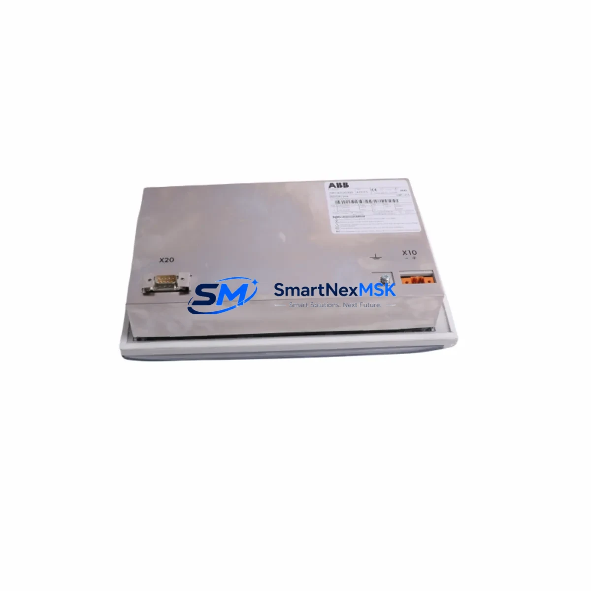
The ABB REF542-PLUS-2RCA029395 is an original spare part for the REF542plus Feeder Protection Relay — one of ABB’s most widely deployed protection devices in medium-voltage switchgear panels, industrial substations, and utility feeder bays. When a REF542plus unit fails or reaches end-of-service life, unplanned downtime in critical power distribution systems can cascade rapidly. Sourcing a verified, tested replacement from a reliable supply channel is the first and most important step in any emergency maintenance response.
This spare is suited for maintenance engineers managing aging protection relay infrastructure, as well as procurement engineers building strategic spare parts inventories for substations running ABB REF542plus-based protection schemes. Whether you are responding to a relay trip fault, conducting a scheduled panel overhaul, or preparing a cold-standby spare for a critical feeder, the REF542-PLUS-2RCA029395 provides a direct, drop-in replacement path with no firmware re-engineering required.
Each unit is pre-shipment tested and dispatched with a 12-month warranty, giving your maintenance team confidence in both the hardware integrity and the supply chain behind it.
Spare Maintenance Table
| Parameter | Specification / Detail |
|---|---|
| SKU / Part Number | REF542-PLUS-2RCA029395 |
| Brand | ABB |
| Series | REF542plus |
| Product Type | Feeder Protection Relay |
| Application | Medium-voltage feeder protection, industrial substation, switchgear panel |
| Mounting | Panel-mount, 19″ rack or flush-mount enclosure (series standard) |
| Communication Interface | IEC 61850, MODBUS RTU, SPA-bus (series dependent) |
| Protection Functions | Overcurrent, earth fault, thermal overload, auto-reclosing (series standard) |
| Auxiliary Supply Voltage | 24–250 V DC / 100–240 V AC (verify nameplate before installation) |
| Origin | Germany |
| Weight | 1,140 g |
| Compatibility | Direct replacement for REF542plus series installations |
| Replacement Scope | Drop-in spare; verify firmware version and I/O configuration before commissioning |
| Pre-shipment Testing | Yes — functional test performed before dispatch |
| Warranty | 12 Months |
Maintenance Planning for Continuous Operation
Effective maintenance planning for a REF542plus-based protection system goes well beyond sourcing the relay itself. When a REF542-PLUS-2RCA029395 is identified as a replacement candidate during a panel inspection or fault investigation, maintenance engineers should simultaneously audit the surrounding components to prevent repeat failures and ensure the restored system meets its original protection performance.
Start with the auxiliary power supply feeding the relay. The REF542plus draws its operating power from the panel’s DC bus — typically supplied by a dedicated 24 V DC or 110 V DC power supply module. If the relay has failed due to a power surge or sustained overvoltage, the supply module itself may be degraded and should be tested or replaced as part of the same maintenance window. Similarly, the panel’s terminal blocks and wiring harness connecting the relay’s binary inputs and outputs to the field — including CT secondary circuits, VT inputs, trip coil circuits, and alarm contacts — should be inspected for insulation breakdown, loose terminations, or corrosion, particularly in humid or high-vibration environments.
The REF542plus communicates upstream to a substation automation system or SCADA via IEC 61850 or SPA-bus. During a relay replacement, the communication module or optical fiber interface card connecting the relay to the station bus should be verified for continuity and correct addressing. If the site uses a COM600 series station automation unit or an RTU560 remote terminal unit as the communication gateway, confirm that the new relay’s IED address and dataset configuration match the existing SCADA mapping before re-energizing the feeder.
Binary I/O expansion modules connected to the REF542plus — used for additional trip outputs, blocking signals, or interlocking with adjacent feeders — must be re-verified after relay replacement. Check that all digital input thresholds and output relay contact ratings remain within specification. If the panel includes a REX521 or REF615 relay on an adjacent feeder sharing the same busbar protection zone, confirm that the inter-relay blocking and trip logic is intact after the swap.
For panels equipped with an ABB CP600 or CP400 series HMI panel, verify that the relay’s MODBUS or IEC 61850 data points are correctly mapped and that all protection status indicators, fault records, and event logs are visible on the HMI after commissioning. Disturbance recorder files from the failed relay should be extracted before removal if the relay is still partially functional, as these records are critical for root-cause analysis.
Finally, ensure that the panel’s miniature circuit breakers protecting the relay’s auxiliary supply and the fuses in the CT secondary circuits are intact and correctly rated. A blown CT secondary fuse is a common and easily overlooked cause of protection relay maloperation that can be mistaken for a relay hardware fault.
Site Replacement Workflow
When replacing the REF542-PLUS-2RCA029395 on site, follow a structured workflow to minimize downtime and avoid commissioning errors. Begin by isolating the feeder and obtaining a safe working permit. De-energize the relay’s auxiliary supply and open all CT secondary shorting links before disconnecting any wiring. Photograph or document all terminal connections before removal — the REF542plus uses a multi-row terminal block arrangement, and incorrect rewiring is a leading cause of post-replacement commissioning failures.
After installing the replacement unit, restore all terminal connections and verify CT secondary circuit continuity with a loop resistance test before removing the shorting links. Upload the relay’s configuration file — previously backed up from the RELAY SETTING TOOL or PCM600 engineering software — to the new unit. Verify all protection settings, including overcurrent pickup levels, time-delay curves, earth fault sensitivity, and auto-reclose sequences, against the approved relay setting schedule.
Perform a secondary injection test using a relay test set to confirm that all protection elements operate correctly at the specified pickup and time settings. Verify binary input and output operation by simulating trip and alarm conditions. Once all tests are passed, restore communication to the station bus and confirm that the SCADA system correctly reflects the relay’s status. Re-energize the feeder under supervision and monitor the relay’s event log for the first 24 hours of operation.
This structured approach keeps total replacement downtime — from isolation to re-energization — within a predictable window, typically 4 to 8 hours for a prepared maintenance team with the correct tools and a pre-tested spare unit on hand.
Spare Parts Support FAQ
Q1: Is the REF542-PLUS-2RCA029395 a direct replacement for all REF542plus variants?
The REF542-PLUS-2RCA029395 is a specific hardware configuration within the REF542plus family. Before ordering, confirm the exact part number on the nameplate of the installed unit, as REF542plus variants differ in I/O count, communication options, and auxiliary voltage range. Our technical team can assist with cross-referencing if you provide the nameplate data or the existing relay’s order code.
Q2: How do I verify compatibility before installation?
Compatibility verification involves three steps: confirming the hardware part number match, verifying that the firmware version of the replacement unit is compatible with your existing configuration file, and checking that the auxiliary supply voltage range matches your panel’s DC bus voltage. We recommend using ABB’s PCM600 tool to compare the configuration of the old and new units before on-site installation.
Q3: What does the 12-month warranty cover?
The 12-month warranty covers hardware defects and functional failures under normal operating conditions. Each unit undergoes a pre-shipment functional test. The warranty does not cover damage resulting from incorrect installation, overvoltage events beyond the relay’s rated input range, or unauthorized modification. Warranty claims are supported with full documentation and replacement dispatch within agreed lead times.
Q4: Can you supply multiple units for a spare parts inventory program?
Yes. We maintain stock of REF542plus series spares and can supply multiple units for planned inventory programs. For sites with multiple REF542plus installations, we recommend holding at least one cold-standby spare per protection zone. Contact our sales team to discuss volume pricing, lead times, and long-term supply agreements for your maintenance program.
© 2026 SMARTNEXMSK. All rights reserved.
Original Source: https://smartnexmsk.com
Contact: sales@smartnexmsk.com | +86 18259474341


