ABB S200-OE4 Retrofit-Ready Analog Output for AC500 Control Systems
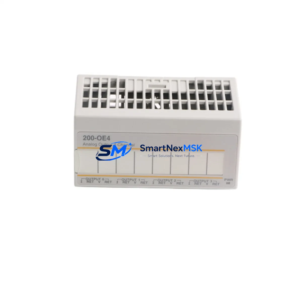
The ABB S200-OE4 is a 4-channel analog output module engineered for the ABB AC500 PLC platform, delivering 0–10 V or 4–20 mA configurable output signals with high-resolution 12-bit conversion. As legacy AC500 installations age and original S200-OE4 units reach end-of-availability, sourcing a verified, tested replacement becomes critical to maintaining production continuity. SMARTNEXMSK maintains ready stock of the S200-OE4 to support planned retrofits, emergency replacements, and phased control-system upgrades across manufacturing, utilities, and process automation environments.
Whether you are replacing a failed module in an existing AC500 PM571 or PM591 CPU rack, migrating a legacy S200 I/O bus to a newer AC500-S or AC500-eCo architecture, or expanding analog output capacity in a multi-rack cabinet, the S200-OE4 slots directly into the standard S200 terminal base without rewiring. The module communicates over the internal S-Bus backplane, and its configuration is managed through ABB Automation Builder (formerly PS501 Control Builder Plus), ensuring full software compatibility with existing PLC programs.
Upgrade Compatibility Table
| Parameter | S200-OE4 Specification | Retrofit Notes |
|---|---|---|
| Output Channels | 4 × analog output (voltage/current) | Matches legacy 4-ch wiring layouts; no terminal rewiring required |
| Signal Range | 0–10 V / 4–20 mA (software-selectable) | Verify field device signal type before swapping; reconfigure via Automation Builder if needed |
| Resolution | 12-bit | Confirm HMI scaling tags match resolution; update if replacing an 8-bit legacy module |
| Backplane Interface | S200 S-Bus (internal) | Compatible with all AC500 V2/V3 CPU racks; verify rack slot addressing in Automation Builder |
| Terminal Base | TA526 / TA527 (standard S200) | Reuse existing terminal base; no new base required for direct swap |
| Communication Protocol | Internal S-Bus; CPU handles PROFIBUS / Modbus / EtherNet/IP upstream | No protocol change at module level; upstream comms handled by CM572-DP or CM589-PNIO |
| Power Supply | Powered via terminal base (24 V DC bus) | Verify PS501 or CP600 power supply capacity; add load budget for new module |
| Installation | DIN rail, snap-on to terminal base | No tools required; confirm DIN rail clearance in existing cabinet |
| Replacement Path | Direct drop-in for S200-OE4 (same generation) | Cross-generation upgrade from older S200 variants requires Automation Builder re-scan |
| Warranty | 12-Month Warranty — all units tested prior to shipment; functional verification report available on request | |
Retrofit Planning for Existing Automation Systems
A successful S200-OE4 retrofit begins well before the module arrives on site. Start by auditing the existing AC500 rack configuration: document every occupied slot, confirm the CPU firmware version (PM571, PM591, or PM595 are common hosts), and export the current Automation Builder project as a backup. If the rack also houses an S200-AI4 analog input module or an S200-DI16 digital input module sharing the same terminal base row, verify that removing the S200-OE4 does not interrupt the S-Bus chain — in most AC500 V2 racks, modules are hot-swap capable, but always consult the rack’s hardware manual before live removal.
Power budget is a frequent oversight in retrofit projects. The S200-OE4 draws its operating power from the 24 V DC internal bus supplied by the rack’s power terminal. If the cabinet also powers an S200-DO16 digital output module driving solenoid valves or relay coils, recalculate the total current draw against the rated output of the installed ABB CP604 or CP607 power supply. Undersized power supplies are a leading cause of intermittent faults after module additions.
For sites migrating from an older AC31 or Advant OCS platform to AC500, the S200-OE4 represents a significant upgrade in signal resolution and diagnostic capability. The transition typically involves remapping I/O addresses in the new Automation Builder project, updating HMI tag databases in ABB CP600 or third-party SCADA systems, and re-verifying PID loop tuning parameters since the higher-resolution output may alter loop response. Communication links to upstream DCS or SCADA via a CM572-DP PROFIBUS-DP master module or a CM589-PNIO PROFINET I/O module remain unaffected at the S200 module level, as all protocol handling is managed by the CPU and communication modules.
Terminal wiring on the TA526 base follows a clearly labeled screw-terminal layout. For 4–20 mA current loop outputs, confirm loop power source (active vs. passive output configuration) and verify field instrument input impedance. For 0–10 V voltage outputs, check for ground loops between the PLC cabinet and field devices — a common issue in long cable runs to remote I/O panels or motor control centers. Label all terminals before disconnecting the old module, and photograph the wiring for reference during reinstallation.
Downtime Control During System Migration
Minimizing production downtime during an S200-OE4 swap requires a structured pre-outage checklist. Before the maintenance window opens, upload the current Automation Builder project to a laptop, verify the backup compiles without errors, and confirm the replacement module’s firmware version matches or is compatible with the CPU’s expected I/O module version. If a firmware mismatch is detected, update the module offline using Automation Builder’s firmware download tool before installation.
During the outage window, follow a strict sequence: place the CPU in STOP mode, de-energize the 24 V DC bus to the affected rack section, remove the failed S200-OE4 from its terminal base, seat the replacement module, re-energize, and perform a hardware scan in Automation Builder to confirm the new module is recognized at the correct slot address. Restore the CPU to RUN mode and monitor all four analog output channels against expected setpoints using the Automation Builder online monitoring view or the connected HMI.
For critical processes where even a brief output interruption is unacceptable, consider pre-staging the replacement module in a parallel test rack with a duplicate program segment. Validate output accuracy against a calibrated reference meter before the live swap. This approach — common in pharmaceutical, water treatment, and power generation applications — reduces the live outage window to under 15 minutes for a single-module replacement. All S200-OE4 units shipped by SMARTNEXMSK undergo pre-shipment functional testing, and a test report is available upon request to support your site acceptance procedure.
Retrofit Support FAQ
Q1: Is the S200-OE4 a direct drop-in replacement for an existing failed unit in my AC500 rack?
Yes. The S200-OE4 uses the standard S200 terminal base (TA526/TA527), so no rewiring is required for a same-generation swap. Slot addressing and I/O mapping in Automation Builder are preserved. If replacing a module from a different S200 generation, perform a hardware re-scan in Automation Builder to confirm recognition.
Q2: What commissioning steps are required after installing the replacement module?
Place the CPU in STOP, install the module, power up, and perform a hardware scan in Automation Builder. Verify the module appears at the correct rack slot. Switch the CPU to RUN and confirm all four output channels are producing expected signals using online monitoring or a calibrated meter at the field terminals. Update HMI scaling if the replacement module has a different resolution than the original.
Q3: Can the S200-OE4 be used in both AC500 V2 and AC500 V3 racks?
The S200-OE4 is compatible with AC500 V2 racks (PM571, PM591, PM595 CPUs) and is also supported in AC500 V3 environments when used with the appropriate terminal base. Confirm compatibility with your specific CPU firmware version in the ABB hardware compatibility matrix or contact SMARTNEXMSK for pre-sale verification.
Q4: What does the 12-month warranty cover, and is pre-shipment testing included?
All S200-OE4 units supplied by SMARTNEXMSK carry a 12-month warranty covering manufacturing defects and functional failures under normal operating conditions. Every unit is functionally tested prior to shipment, and a test report is available on request. Warranty claims are processed directly — contact sales@smartnexmsk.com with your order reference and fault description.
© 2026 SMARTNEXMSK. All rights reserved.
Original Source: https://smartnexmsk.com
Contact: sales@smartnexmsk.com | +86 18259474341


