ABB SAFT113POW Retrofit-Ready Power Supply for SAFT Series Control Systems
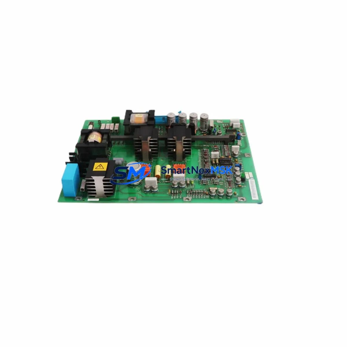
The ABB SAFT113POW is a dedicated power supply module engineered for the ABB SAFT Series AC drive platform — one of the most widely deployed variable-frequency drive families in industrial automation. As legacy SAFT Series installations approach end-of-life or require capacity upgrades, the SAFT113POW serves as the authoritative retrofit solution, delivering stable DC bus power to the drive’s control electronics while maintaining full backward compatibility with existing backplane wiring, terminal layouts, and control logic.
For maintenance engineers managing aging drive cabinets, the SAFT113POW eliminates the need for full drive replacement. Whether you are restoring a tripped system after a power supply fault, upgrading a control cabinet to handle expanded I/O loads, or migrating from an obsolete SAFT110POW or SAFT112POW module, the SAFT113POW provides a direct, validated replacement path. Its regulated output rails support the full range of SAFT Series control boards, including the SAFT121CON control board and SAFT122CON interface board, ensuring that existing program logic, parameter sets, and HMI screen mappings remain intact after the swap.
Procurement teams sourcing discontinued ABB drive components will find the SAFT113POW consistently available through SMARTNEXMSK’s verified industrial inventory. Each unit is subject to pre-shipment functional testing covering output voltage regulation, inrush current behavior, and thermal performance — critical checkpoints for components destined for continuous-duty industrial environments.
Upgrade Compatibility Table
| Parameter | Details |
|---|---|
| Compatible Platform | ABB SAFT Series AC Drives (SAFT 110 / 115 / 120 / 130 / 140 / 150) |
| Direct Replacement For | SAFT110POW, SAFT112POW, SAFT113POW (original), SAFT114POW |
| Backplane Interface | Standard SAFT Series backplane connector — no adapter required |
| Terminal Wiring | Matches original terminal block layout; no rewiring required |
| Communication Compatibility | Compatible with SAFT Series fieldbus adapters (PROFIBUS, Modbus RTU, DeviceNet) |
| Installation Requirement | DIN rail or panel mount; standard SAFT Series module slot |
| Commissioning Note | Verify module address DIP switch settings match original configuration before power-on |
| Program Compatibility | No PLC program changes required; existing parameter sets retained |
| HMI Screen Impact | None — existing HMI screens and drive parameter mappings remain valid |
| Warranty | 12-Month Warranty | Pre-shipment functional testing included |
Retrofit Planning for Existing Automation Systems
A successful SAFT113POW retrofit begins well before the module arrives on site. Engineers should start by auditing the existing control cabinet to confirm the power supply slot dimensions, backplane connector type, and the current firmware revision loaded on the SAFT121CON control board. In many legacy installations, the SAFT113POW shares a cabinet with the SAFT122CON interface board, SAFT123IOB I/O expansion board, and SAFT131ADP fieldbus adapter — all of which must remain powered and communicating during the transition to avoid cascading faults.
Terminal block verification is a mandatory pre-swap step. The SAFT113POW’s DC output terminals must be matched against the existing wiring diagram to confirm polarity, conductor gauge, and torque specifications. In installations where the original SAFT110POW or SAFT112POW has been in service for more than a decade, terminal oxidation and conductor fatigue are common — this is the ideal moment to replace terminal ferrules and inspect the SAFT Series backplane ribbon cable for wear.
For sites running PROFIBUS DP or Modbus RTU communication links through a SAFT131ADP or SAFT132ADP fieldbus adapter, the communication link should be placed in a safe hold state before the power supply is removed. This prevents the upstream PLC — often a Siemens S7-300, Allen-Bradley SLC 500, or ABB AC500 — from logging spurious communication fault alarms that could trigger interlock sequences in adjacent control loops.
Where the SAFT Series drive is integrated with a local operator panel or remote HMI via the SAFT141CDP control panel interface, the HMI connection should be documented and the panel placed in local manual mode prior to the swap. After the SAFT113POW is seated and powered, the HMI communication link should be re-established and all drive status screens verified against the pre-swap baseline. Parameter group 01 (drive identification) and parameter group 10 (start/stop logic) are the first checkpoints in any post-swap commissioning sequence.
I/O expansion modules such as the SAFT123IOB should be re-scanned after power restoration to confirm that all analog and digital I/O channels are reporting correctly. Any discrepancy in I/O channel status at this stage typically indicates a module address conflict — resolved by adjusting the DIP switch settings on the SAFT113POW or the adjacent I/O module to restore the original address map.
Downtime Control During System Migration
Minimizing production downtime during a SAFT113POW swap requires a structured hot-swap protocol. Begin by exporting the full drive parameter set using the ABB DriveWindow or DriveStudio software tool connected via the SAFT141CDP or a USB-to-serial programming cable. Store the parameter backup on a local engineering laptop and a network share simultaneously — this redundancy is essential if the replacement module requires a factory reset before commissioning.
The physical swap itself — removing the failed SAFT110POW or SAFT112POW and seating the SAFT113POW — typically takes under 15 minutes for a trained technician familiar with the SAFT Series module locking mechanism. The critical time investment is in pre-swap preparation and post-swap verification: confirming output voltage levels with a calibrated multimeter before reconnecting the backplane, verifying that the SAFT121CON control board recognizes the new module, and running a no-load power-on test before re-engaging the motor circuit.
For continuous-process environments where even a 30-minute outage carries significant cost, SMARTNEXMSK recommends maintaining one SAFT113POW as a cold-standby spare in the site’s MRO inventory. This eliminates lead-time risk entirely and reduces mean time to repair (MTTR) to the duration of the physical swap and commissioning sequence alone.
Retrofit Support FAQ
Q1: Is the SAFT113POW a direct drop-in replacement for the SAFT110POW and SAFT112POW?
Yes. The SAFT113POW is mechanically and electrically compatible with the SAFT110POW and SAFT112POW in all standard SAFT Series drive configurations. No backplane modifications, wiring changes, or program edits are required. Verify DIP switch address settings match the original module before power-on.
Q2: Will my existing PLC program and HMI screens remain valid after the swap?
Yes. The SAFT113POW does not alter the drive’s parameter memory or communication address. Existing PLC logic, HMI screen bindings, and fieldbus node addresses are preserved. A full parameter backup prior to the swap is still recommended as a precautionary measure.
Q3: What pre-shipment testing is performed on each SAFT113POW unit?
Each unit undergoes functional testing covering DC output voltage regulation across all output rails, inrush current behavior at rated load, and thermal performance under continuous-duty conditions. A test report is available upon request. All units ship with a 12-month warranty covering manufacturing defects and functional failures under normal operating conditions.
Q4: How quickly can a SAFT113POW be sourced for an emergency breakdown situation?
SMARTNEXMSK maintains verified stock of the SAFT113POW and can confirm availability and dispatch timeline within one business day. Express shipping options are available for emergency breakdown orders. Contact sales@smartnexmsk.com or call +86 18259474341 for urgent sourcing inquiries.
© 2026 SMARTNEXMSK. All rights reserved.
Original Source: https://smartnexmsk.com
Contact: sales@smartnexmsk.com | +86 18259474341


