ABB SDCS-COM-1 3BSE005028R1 Retrofit-Ready Drive Link for DCS800 Control Systems
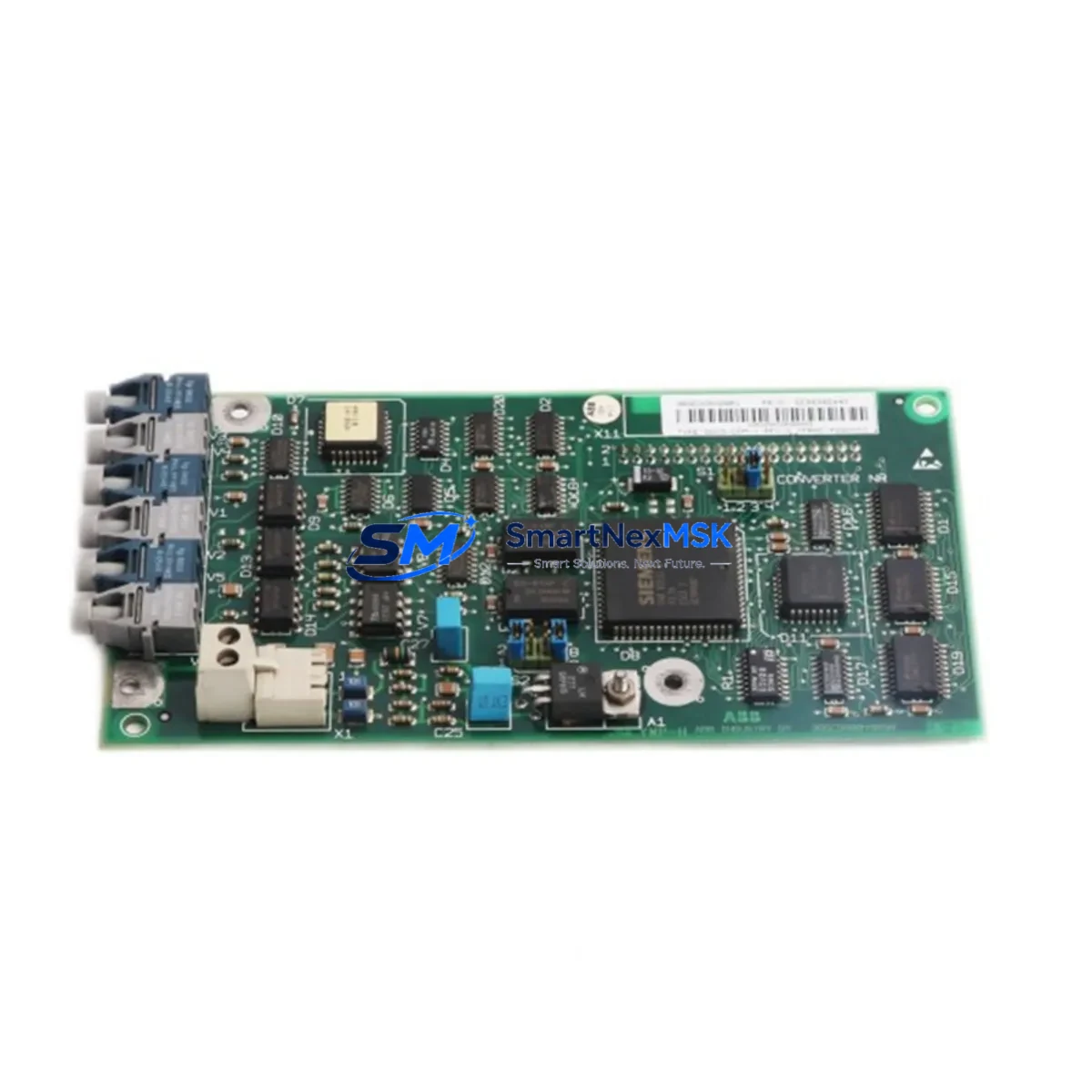
The ABB SDCS-COM-1 (part number 3BSE005028R1) is a drive communication board engineered for the DCS800 series of DC drives, providing a robust and reliable link between the drive control unit and higher-level automation networks. As legacy DC drive installations age and original communication boards reach end-of-life, the SDCS-COM-1 has become one of the most sought-after retrofit and replacement components in industrial control system modernization projects. Whether you are restoring a failed drive, upgrading an aging production line, or migrating from an obsolete communication architecture, this module delivers the compatibility and performance your system demands.
Sourced from verified supply channels and subjected to pre-shipment functional testing, every SDCS-COM-1 3BSE005028R1 unit shipped by SMARTNEXMSK is backed by a 12-month warranty, ensuring confidence in both the component and the continuity of your operation.
Upgrade Compatibility Table
| Parameter | Details |
|---|---|
| Compatible Drive Series | ABB DCS800 (all frame sizes) |
| Replaces / Supersedes | SDCS-COM-1 (earlier revisions), legacy DCS500 communication adapters (with firmware update) |
| Interface / Backplane | Slot-mount on DCS800 control board; standard SDCS slot connector |
| Communication Compatibility | DDCS (Distributed Drive Control System) fiber-optic protocol; compatible with AC800M, AC500, and third-party DDCS masters |
| Installation Requirement | No hardware modification required; direct plug-in replacement; verify drive firmware version ≥ 3.x for full feature support |
| Retrofit Recommendation | Confirm node address DIP switch settings match original configuration before power-on; re-download drive parameters via DriveWindow or DriveStudio after swap |
| Commissioning Focus | DDCS node address, fiber-optic channel assignment, dataset mapping, and master-follower link verification |
| Warranty | 12 months from date of shipment; covers manufacturing defects and functional failure under normal operating conditions |
Retrofit Planning for Existing Automation Systems
Replacing the SDCS-COM-1 3BSE005028R1 in an operating facility requires careful pre-work to avoid extended downtime and configuration loss. Before removing the failed board, document the existing DIP switch positions for the DDCS node address — these settings determine how the DCS800 drive is identified on the fiber-optic ring connecting it to the master controller, which may be an ABB AC800M PLC, an AC500 controller, or a third-party DDCS master.
In multi-drive systems, the DCS800 units are often daisy-chained via DDCS fiber-optic cables, with each drive assigned a unique channel and node address. Disrupting this chain without proper isolation can cause the entire drive group to fault. It is advisable to isolate the affected drive from the DDCS ring using a fiber-optic bypass or by temporarily reconfiguring the master dataset mapping before the board swap.
Power supply integrity is a critical pre-check. The SDCS-COM-1 draws its operating voltage from the DCS800 internal 24 VDC auxiliary supply rail, shared with other option boards such as the SDCS-IOB-3 I/O expansion board and the SDCS-FEX-2 field excitation board. Verify that the auxiliary supply capacity is not already at its limit before adding or replacing communication boards. An overloaded auxiliary rail can cause intermittent resets or communication errors that are difficult to diagnose in the field.
Terminal wiring on the SDCS-COM-1 is limited to the fiber-optic TX/RX connectors — there are no screw terminals on this board. However, the broader retrofit context often involves checking the wiring integrity of adjacent modules. If the retrofit is part of a larger control cabinet upgrade, this is an ideal time to inspect the SDCS-IOB-21 digital I/O board connections, verify the SDCS-PIN-51 pulse encoder interface wiring, and confirm that the RMIO-11 or RMIO-12 main control board is operating within its rated temperature range.
For facilities migrating from older DCS500 series drives to DCS800, the SDCS-COM-1 plays a central role in the communication architecture transition. The DCS500 used a different variant of the DDCS protocol, and while the physical fiber-optic connectors are compatible, dataset definitions and parameter mapping must be re-engineered in the master PLC program. Engage your ABB DriveStudio or DriveWindow software to export the original DCS500 parameter set before decommissioning, and use it as a reference baseline when commissioning the DCS800 replacement.
HMI screens connected to the drive system — whether running on ABB Panel Builder, Siemens WinCC, or a third-party SCADA — will need their drive communication tags verified after the board swap. Dataset addresses and parameter numbers may differ between drive generations, and mismatched tags can result in incorrect speed references, torque limits, or fault displays on the operator panel. Schedule HMI tag verification as a mandatory commissioning step, not an afterthought.
In systems where the DCS800 is integrated with a broader automation platform — for example, an ABB System 800xA or a Siemens PCS 7 DCS — the DDCS communication link feeds process data to the distributed control layer. After replacing the SDCS-COM-1, confirm that all dataset subscriptions in the DCS are re-established and that historian tags are receiving live values before returning the drive to automatic control mode.
Downtime Control During System Migration
Minimizing production downtime during a drive communication board replacement requires a structured approach. Begin with a full parameter backup of the DCS800 using DriveWindow Light or DriveStudio — this captures all application parameters, speed references, ramp settings, and protection thresholds. Store the backup file on a dedicated commissioning laptop and verify it can be restored before proceeding with the physical swap.
If the production process allows, perform the board replacement during a planned maintenance window rather than as an emergency repair. Pre-stage the replacement SDCS-COM-1 3BSE005028R1 with the correct node address DIP switch settings configured before entering the cabinet. This reduces the time the drive is offline to the minimum required for the physical swap and parameter restore — typically 30 to 60 minutes for an experienced technician.
For critical continuous processes where even a brief stop is costly, consider pre-commissioning the replacement drive on a test bench using a spare SDCS-IOB-3 I/O board and a bench power supply to simulate the field environment. Load the backed-up parameter set, verify DDCS communication with a portable master, and confirm all datasets are mapping correctly before the scheduled maintenance window. This approach compresses field commissioning time to a final verification step rather than a full setup procedure.
After the board is installed and the drive is powered up, follow a structured commissioning sequence: verify auxiliary power, confirm DDCS link status LEDs, restore parameters from backup, run the drive in local control mode to verify speed response, then transfer to remote/automatic control and confirm all HMI and SCADA tags are live. Document the commissioning results and retain the parameter backup file as part of the plant maintenance record.
Retrofit Support FAQ
Q1: Is the SDCS-COM-1 3BSE005028R1 a direct drop-in replacement for earlier SDCS-COM-1 revisions?
Yes. The 3BSE005028R1 part number covers the current production revision of the SDCS-COM-1 and is backward compatible with all DCS800 frame sizes. No hardware modification is required. Verify that the drive firmware is version 3.x or later for full feature compatibility; earlier firmware versions may not support all dataset functions of the current board revision.
Q2: What commissioning steps are required after installing the replacement board?
After physical installation, set the DDCS node address DIP switches to match the original configuration, power up the drive, and verify the DDCS link status LED is active. Restore the parameter backup using DriveWindow or DriveStudio, run the drive in local mode to confirm speed and torque response, then return to remote control and verify all HMI and SCADA communication tags are live. Document all commissioning results.
Q3: Can the SDCS-COM-1 be used in a system migrating from DCS500 to DCS800?
Yes, but the migration requires re-engineering the DDCS dataset mapping in the master controller program. The physical fiber-optic interface is compatible, but parameter numbers and dataset structures differ between DCS500 and DCS800. Export and archive the original DCS500 parameter set before decommissioning, and use it as a reference when configuring the DCS800 and its SDCS-COM-1 communication board.
Q4: What does the 12-month warranty cover, and how is it handled?
The 12-month warranty covers manufacturing defects and functional failure under normal operating conditions from the date of shipment. If a unit fails within the warranty period, contact SMARTNEXMSK with the order reference and a description of the fault. We will arrange a replacement or repair at no additional cost. All units undergo pre-shipment functional testing to minimize the risk of DOA (dead-on-arrival) failures.
© 2026 SMARTNEXMSK. All rights reserved.
Original Source: https://smartnexmsk.com
Contact: sales@smartnexmsk.com | +86 18259474341


