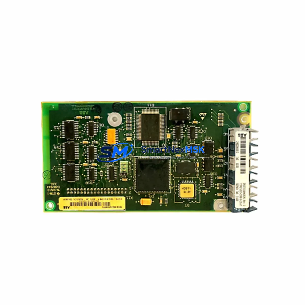
ABB SDCS-COM-5 3BSE006567R1 Retrofit-Ready Communication Module for DCS600 Control Systems
The ABB SDCS-COM-5 (part number 3BSE006567R1) is a dedicated communication module engineered for the ABB DCS600 DC drive series, one of the most widely deployed DC drive platforms in heavy industrial environments. As legacy DCS600 installations age and OEM support windows close, the SDCS-COM-5 has become a critical retrofit component for engineers tasked with extending the operational life of existing drive systems without undertaking a full platform migration. Whether you are replacing a failed unit, building a spare-parts buffer, or executing a phased control-system upgrade, the SDCS-COM-5 3BSE006567R1 provides a verified drop-in solution that preserves your existing wiring, program logic, and communication architecture.
Sourced directly from authorized distribution channels and subject to full functional testing prior to shipment, every unit supplied by SMARTNEXMSK is backed by a 12-month warranty covering manufacturing defects and operational failures under normal service conditions. Stock is maintained on-hand to support urgent breakdown orders and planned maintenance schedules alike.
Upgrade Compatibility Table
| Parameter | Details |
|---|---|
| Part Number | SDCS-COM-5 / 3BSE006567R1 |
| Compatible Drive Series | ABB DCS600 (DCS601, DCS602, DCS603, DCS604) |
| Direct Replacement For | SDCS-COM-1, SDCS-COM-3 (verify firmware revision before swap) |
| Communication Protocols | DDCS (Distributed Drive Control System) fiber-optic link; compatible with NDIO, NAMC, and NPOW adapter boards |
| Backplane Interface | SDCS control board slot — direct plug-in, no adapter required |
| Installation Requirement | Power-off installation; verify SDCS-CON-2 or SDCS-CON-3 control board compatibility |
| Firmware Compatibility | Compatible with DCS600 firmware versions 5.x and above; confirm via CDP tool before commissioning |
| Commissioning Tool | ABB CDP Control Panel or DriveWindow 2 PC software |
| Retrofit Recommendation | Suitable for direct swap in existing DCS600 cabinets; no mechanical modification required |
| Warranty | 12 Months — covers manufacturing defects and functional failures under normal operating conditions |
| Origin | Germany (DE) |
| Pre-Shipment Testing | Full functional test performed on every unit |
Retrofit Planning for Existing Automation Systems
Successful integration of the SDCS-COM-5 3BSE006567R1 into an existing DCS600 installation requires a structured pre-retrofit assessment. Begin by documenting the current drive configuration using the ABB CDP Control Panel or DriveWindow 2 software to export all parameter sets before any hardware is disturbed. This parameter backup is essential — it protects the tuned speed-loop, current-loop, and field-weakening settings that have been optimized for your specific motor and load profile over years of operation.
Next, verify the host control board. The SDCS-COM-5 is designed to seat into the communication slot of the SDCS-CON-2 or SDCS-CON-3 control board. If your installation is running an older SDCS-CON-1 board, a control board upgrade may be required before the SDCS-COM-5 can be installed. In many retrofit projects, engineers elect to replace the SDCS-CON-2 control board and the SDCS-COM-5 communication module simultaneously to establish a clean, fully supported hardware baseline.
The SDCS-COM-5 communicates over the ABB DDCS fiber-optic network, which connects the DCS600 drive to higher-level controllers such as the ABB AC800M DCS controller or the AC500 PLC series. Inspect the existing fiber-optic cables for physical damage, connector contamination, and bend-radius violations before reconnecting. Dirty or damaged fiber connectors are a leading cause of intermittent DDCS communication faults after a module swap. Clean all connectors with an appropriate fiber-optic cleaning kit and verify optical power levels if test equipment is available.
On the I/O side, confirm that the NDIO digital I/O extension module and any NAMC application module boards installed in the drive are compatible with the firmware version supported by the replacement SDCS-COM-5. In multi-drive systems where several DCS600 units share a common DDCS ring, the module address (parameter 70.01 NODE ADDRESS) must be set correctly on the replacement unit before the ring is re-energized to avoid address conflicts that can disrupt the entire drive network.
For installations that include an ABB Panel Bus or Modbus RTU link to a SCADA or DCS system, verify that the communication adapter — typically an NMBP-01 Modbus adapter or an NPBA-12 PROFIBUS adapter — is correctly configured and that the host system’s polling cycle is compatible with the restored drive node. In some older installations, the HMI screens built on ABB IndustrialIT or a third-party SCADA platform reference drive parameters by node address; confirm that all HMI faceplates and alarm tags resolve correctly after the module is replaced and the drive is back online.
Power supply integrity is another critical checkpoint. The SDCS-COM-5 draws its logic supply from the SDCS-POW-1 or NPOW power supply board within the drive. Before commissioning the replacement module, measure the 24 VDC auxiliary supply voltage at the control board connector under load. A degraded SDCS-POW-1 power supply board that is marginal on voltage regulation can cause erratic behavior in a new communication module and is frequently misdiagnosed as a module fault. Replacing a worn SDCS-POW-1 alongside the SDCS-COM-5 is a recommended best practice in drives that have been in service for more than ten years.
Finally, if the DCS600 drive is part of a coordinated multi-drive system — for example, a winder, unwinder, and dancer-roll drive set — plan the retrofit sequence so that the master drive and follower drives are brought back online in the correct order. The DDCS master-follower configuration stored in the drive parameters must be verified after any communication module replacement to ensure that torque-sharing and speed-reference distribution are functioning correctly before the line is restarted under load.
Downtime Control During System Migration
Minimizing unplanned downtime is the primary concern for any maintenance team executing a communication module replacement on a running production line. The most effective strategy is to treat the SDCS-COM-5 replacement as a planned maintenance event rather than an emergency repair. Pre-stage the replacement module, verify its firmware revision against your drive’s current firmware, and prepare a printed copy of the drive’s parameter list before the maintenance window opens.
During the swap, work systematically: isolate the drive from the DDCS ring by disconnecting the fiber-optic cables at the module connectors rather than at the remote end, which preserves the ring topology for other drives in the network. Label all fiber connections before removal. The SDCS-COM-5 is a plug-in module — no soldering or field wiring modification is required. Seat the replacement module firmly, reconnect the fiber cables in the correct TX/RX orientation, and restore auxiliary power before re-energizing the main DC bus.
After power-up, use the CDP Control Panel to verify that the drive recognizes the communication module and that the DDCS link status indicators show a healthy ring. Reload the saved parameter set using DriveWindow 2 or the CDP panel’s parameter copy function. Run the drive at reduced speed in local control mode before transferring to remote control from the DCS or PLC. This staged commissioning approach — local verification before remote handover — is the single most effective method for protecting the original program logic and maintaining field control continuity throughout the migration.
For sites where even a brief production interruption is unacceptable, consider maintaining a pre-configured hot-spare SDCS-COM-5 unit with the drive parameters already loaded. SMARTNEXMSK can supply units in quantity to support spare-parts programs, and our technical team can advise on parameter pre-loading procedures for your specific DCS600 variant.
Retrofit Support FAQ
Q1: Is the SDCS-COM-5 3BSE006567R1 a direct replacement for the SDCS-COM-1 or SDCS-COM-3?
The SDCS-COM-5 is the current-generation communication module for the DCS600 series and is functionally compatible with applications previously served by the SDCS-COM-1 and SDCS-COM-3. However, you must verify the firmware revision of your SDCS-CON-2 or SDCS-CON-3 control board before installation, as some early firmware versions may require an update to fully support the SDCS-COM-5 feature set. Contact our technical team with your drive nameplate data and we will confirm compatibility before shipment.
Q2: What commissioning steps are required after installing the replacement module?
After physical installation, restore the drive parameter set from your pre-retrofit backup using DriveWindow 2 or the CDP Control Panel. Set the DDCS node address (parameter 70.01) to match the original configuration. Verify fiber-optic link status on the CDP panel, then run the drive in local mode at reduced speed to confirm correct operation before returning to remote DCS/PLC control. A full I/O check and speed-reference verification should be completed before resuming production.
Q3: How do I verify wiring and terminal compatibility before the swap?
The SDCS-COM-5 connects to the DCS600 drive via the control board’s communication slot — there is no field wiring directly to the module itself. All field wiring (analog references, digital I/O, encoder feedback) connects to the SDCS-CON-2/CON-3 control board terminals, which remain undisturbed during a communication module replacement. Verify that the fiber-optic cable connectors (HFBR type) are clean and undamaged before reconnection.
Q4: What does the 12-month warranty cover, and how is it claimed?
Every SDCS-COM-5 3BSE006567R1 supplied by SMARTNEXMSK is covered by a 12-month warranty from the date of shipment. The warranty covers manufacturing defects and functional failures under normal operating conditions, including DDCS communication failures, module recognition faults, and power supply interface issues. Warranty claims are processed by contacting our sales team with the order reference and a description of the fault. We will arrange return shipping and provide a replacement unit or full refund at our discretion. Units damaged by incorrect installation, overvoltage, or physical impact are not covered under warranty.
© 2026 SMARTNEXMSK. All rights reserved.
Original Source: https://smartnexmsk.com
Contact: sales@smartnexmsk.com | +86 18259474341


