ABB SDCS-COM-81 3ADT314900R1002 Maintenance-Ready Spare DCS800: Spare Replacement and Industrial Downtime Risk Control
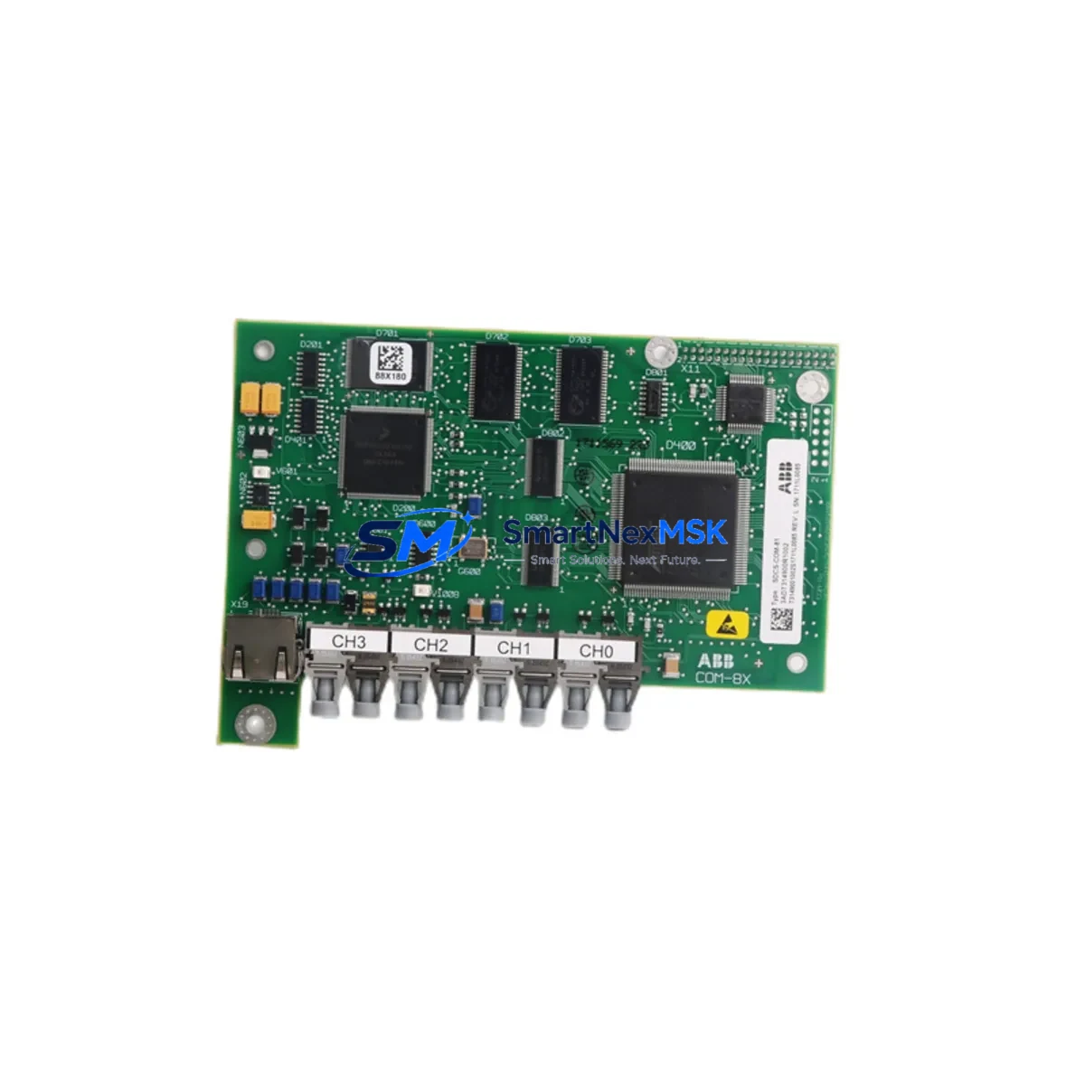
The ABB SDCS-COM-81 (part number 3ADT314900R1002) is a serial communication field kit designed for the DCS800 series DC drive platform. In industrial environments where DC drive systems underpin critical production lines, conveyor systems, winding machines, and process control loops, the availability of a verified, original spare communication module is a direct factor in minimizing unplanned downtime. This listing provides maintenance engineers and MRO procurement teams with a tested, ready-to-ship replacement unit backed by a 12-month warranty and full pre-shipment inspection.
The SDCS-COM-81 module enables serial fieldbus communication between the DCS800 drive and the plant-level control network. Its failure — whether due to electrical transients, aging connectors, firmware incompatibility after a control system upgrade, or physical damage during cabinet maintenance — can render an otherwise functional drive unable to receive speed references, torque commands, or status feedback from the PLC or DCS. Stocking this module as a critical spare is a standard recommendation in any DCS800 preventive maintenance program.
Spare Maintenance Table
| Parameter | Specification / Detail |
|---|---|
| Part Number | SDCS-COM-81 / 3ADT314900R1002 |
| Brand | ABB |
| Compatible Series | DCS800 DC Drive Series |
| Module Function | Serial Communication Field Kit (Fieldbus Adapter) |
| Communication Interface | Serial fieldbus (RS-485 / proprietary ABB protocol depending on configuration) |
| Origin | Germany (DE) |
| Product Condition | Original, New or Refurbished-to-OEM-spec (confirmed per unit) |
| Compatibility | DCS800-S, DCS800-A, DCS800-EP variants; verify drive firmware revision before installation |
| Installation Environment | Industrial control cabinet; IP20 internal mounting; operating temp 0–55°C |
| Maintenance Interval | Inspect connectors and communication status LEDs during scheduled drive service |
| Pre-Shipment Testing | Functional communication test performed before dispatch |
| Warranty | 12 Months from date of shipment |
| Lead Time | In-stock units ship within 1–3 business days |
Maintenance Planning for Continuous Operation
When replacing the SDCS-COM-81 communication module in a DCS800 drive, a thorough site inspection of the surrounding electrical system is essential to prevent repeat failures and confirm system integrity. Maintenance engineers should treat this replacement as an opportunity to audit the full drive cabinet and associated control loop.
Begin with the DCS800 power supply board (SDCS-POW-4) — verify DC bus voltage levels and check for capacitor aging or ripple anomalies that could have contributed to communication module stress. Inspect the SDCS-CON-4 control board, which interfaces directly with the communication module; a degraded control board can cause intermittent fieldbus faults that are misdiagnosed as communication module failures. Check the SDCS-FEX-2 field excitation module if the drive controls a separately excited DC motor, as field current instability can generate electrical noise that disrupts serial communication.
Review the 24 VDC auxiliary power supply feeding the drive’s control electronics — voltage sags or ripple on this rail are a common root cause of communication resets. Inspect terminal blocks and signal wiring on the fieldbus connector; corroded or loose terminals on RS-485 lines cause intermittent communication errors that can be mistaken for module failure. If the DCS800 is integrated into a PROFIBUS or Modbus network, verify the network termination resistors and cable shielding continuity.
For drives connected to an ABB AC500 PLC or a third-party DCS, confirm that the communication adapter configuration parameters (node address, baud rate, protocol selection) are correctly documented before removing the old module, as these settings must be replicated on the replacement unit. If the plant uses ABB DriveWindow or DriveStudio for drive parameterization, ensure the engineering workstation is available on-site during commissioning of the replacement module.
Additionally, inspect the I/O extension modules (SDCS-IOB-3 or equivalent) mounted in the same drive cabinet for signs of overheating or connector wear. Check any signal isolators on analog speed reference or torque feedback signals — degraded isolation can introduce ground loops that affect communication stability. Verify the condition of cabinet door seals and cooling fan filters; excessive dust ingress is a leading cause of premature failure in communication electronics within drive cabinets.
Site Replacement Workflow
Step 1 — Pre-replacement documentation: Record all drive parameters using DriveWindow or the drive’s keypad before powering down. Note the current communication module firmware version, node address, and protocol settings. Photograph the existing wiring and connector orientation.
Step 2 — Safe isolation: Follow LOTO (Lockout/Tagout) procedures. Isolate the main AC supply and allow the DC bus capacitors to discharge fully (minimum 5 minutes after isolation, verify with a calibrated voltmeter). Disconnect the 24 VDC auxiliary supply.
Step 3 — Module removal: Disconnect the fieldbus cable connector from the SDCS-COM-81. Release the module retention clips and carefully extract the module from the drive’s option slot. Avoid touching the PCB edge connectors.
Step 4 — Replacement installation: Insert the new SDCS-COM-81 (3ADT314900R1002) into the option slot until the retention clips engage. Reconnect the fieldbus cable. Restore auxiliary power and verify the module’s status LEDs indicate normal initialization.
Step 5 — Parameter restore and commissioning: Restore drive parameters from the saved backup. Configure communication parameters on the new module to match the documented settings. Perform a communication test from the PLC or DCS — verify cyclic data exchange, status word readback, and speed reference write.
Step 6 — Return to service: Restore main power, perform a no-load test run, then a loaded test run at reduced speed before returning the drive to full production duty. Document the replacement in the plant maintenance management system (CMMS).
This workflow is applicable whether replacing a failed module on an emergency basis or performing a planned swap during a scheduled maintenance window. The SDCS-COM-81 is a direct plug-in replacement for the same slot position across compatible DCS800 variants, eliminating the need for mechanical modifications and minimizing commissioning time.
Spare Parts Support FAQ
Q1: What is the expected service life of the SDCS-COM-81, and when should it be proactively replaced?
The SDCS-COM-81 does not have a fixed mandatory replacement interval under normal operating conditions. However, in drives that have been in service for 10+ years, proactive replacement during a planned shutdown is advisable — particularly if the drive has experienced repeated communication faults, the cabinet environment has been dusty or humid, or the original module predates a firmware revision that addressed known communication stability issues. Stocking one spare unit per critical drive is a standard MRO best practice.
Q2: How is compatibility with my specific DCS800 variant confirmed before shipment?
Provide your drive’s full nameplate data (type code, serial number, and firmware version) when placing your order. Our technical team will cross-reference the module part number 3ADT314900R1002 against ABB’s compatibility matrix for DCS800-S, DCS800-A, and DCS800-EP variants. Pre-shipment functional testing is performed on all units, and a test report is available upon request.
Q3: Can the SDCS-COM-81 be used to replace an older communication module from a previous DCS800 generation?
In most cases, yes — the SDCS-COM-81 is designed to replace earlier serial communication options in the DCS800 option slot. However, if the original module used a different fieldbus protocol (e.g., PROFIBUS DP via SDCS-COM-8 vs. serial via SDCS-COM-81), the replacement must match the protocol in use on your plant network. Confirm the fieldbus type with your control system documentation before ordering.
Q4: What does the 12-month warranty cover, and what is the return process if a fault is found after installation?
The 12-month warranty covers manufacturing defects and functional failures under normal operating conditions from the date of shipment. It does not cover damage caused by incorrect installation, overvoltage events, or operation outside specified environmental limits. If a fault is identified after installation, contact sales@smartnexmsk.com with the order reference and a description of the fault. Our team will arrange a replacement dispatch or technical support within 2 business days.
© 2026 SMARTNEXMSK. All rights reserved.
Original Source: https://smartnexmsk.com
Contact: sales@smartnexmsk.com | +86 18259474341


