ABB SDCS-PIN-48 3BSE004939R0002 Retrofit-Ready Pulse Transformer for DCS800 Control Systems
The ABB SDCS-PIN-48 (3BSE004939R0002) is a pulse transformer interface board engineered for the ABB DCS800 series DC drive platform. As legacy DC drive installations age and original spare parts become increasingly scarce, the SDCS-PIN-48 serves as a critical retrofit and replacement component — enabling maintenance teams to restore full drive functionality without committing to a complete drive replacement or costly system redesign. Whether you are managing a planned upgrade, responding to an unplanned failure, or building a strategic spare parts inventory for long-term DCS800 lifecycle support, the SDCS-PIN-48 3BSE004939R0002 is a verified, tested solution available for immediate dispatch.
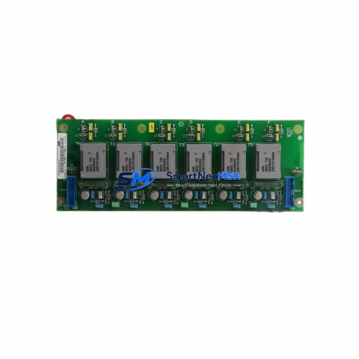
The SDCS-PIN-48 board interfaces directly with the DCS800 drive’s thyristor firing circuit, translating low-level gate pulse signals from the control board into the isolated, high-voltage pulses required to trigger the power bridge SCRs. Degradation or failure of this board typically manifests as erratic firing angles, asymmetric phase control, overcurrent trips, or complete loss of DC output — symptoms that can be misdiagnosed as power bridge or armature circuit faults. Replacing the SDCS-PIN-48 with a tested unit is frequently the fastest path to drive restoration, minimizing unplanned downtime on critical production equipment.
Upgrade Compatibility Table
| Parameter | Specification / Recommendation |
|---|---|
| Part Number | SDCS-PIN-48 / 3BSE004939R0002 |
| Brand | ABB |
| Compatible Platform | ABB DCS800 Series DC Drives |
| Board Function | Pulse Transformer Interface (SCR Gate Firing) |
| Replaces / Supersedes | Earlier SDCS-PIN-4x variants (verify drive firmware revision) |
| Interface Type | Direct plug-in to DCS800 control board backplane connector |
| Installation Requirement | No hardware modification required; direct board swap |
| Communication Compatibility | Compatible with SDCS-COM-8 (PROFIBUS), SDCS-COM-81 (DeviceNet), and fieldbus adapter modules |
| Firmware Dependency | No firmware change required for direct replacement |
| Commissioning Focus | Verify firing angle calibration and gate pulse symmetry after installation |
| Country of Origin | Germany |
| Condition | Tested, inspected, ready to ship |
| Warranty | 12 Months |
Retrofit Planning for Existing Automation Systems
A successful SDCS-PIN-48 retrofit begins well before the board is physically installed. Maintenance engineers should first confirm the DCS800 drive’s hardware revision and firmware version — typically found on the SDCS-CON-4 main control board label — to ensure full compatibility with the replacement pulse transformer board. The SDCS-CON-4 governs the firing angle calculation and gate pulse timing; any mismatch between the control board revision and the pulse interface board can result in asymmetric SCR triggering or protection faults at startup.
Before removing the failed board, document the existing terminal wiring on the SDCS-IOB-3 I/O extension board and any connected analog or digital signal cables. In many DCS800 installations, the I/O board carries speed reference signals, current feedback wiring, and enable/inhibit logic from the plant control system — often a PLC such as an ABB AC500 or a third-party controller. Photograph or sketch the wiring layout before disconnection to eliminate re-commissioning errors.
If the drive communicates with a supervisory system via SDCS-COM-8 (PROFIBUS DP) or SDCS-COM-81 (DeviceNet), verify that the fieldbus node address and baud rate settings stored in the drive’s parameter memory are backed up before the board swap. These settings are retained in the SDCS-CON-4 non-volatile memory and are not affected by replacing the SDCS-PIN-48, but confirming this before work begins prevents unnecessary troubleshooting after restart.
For drives equipped with an SDCS-FEX-2 field excitation module, the field current setpoint and ramp parameters should also be recorded. The field excitation circuit operates independently of the pulse transformer board, but a complete drive restart after the repair will cycle through the field forcing sequence — and having the correct parameters on hand accelerates the return-to-service process.
In installations where the DCS800 drive is monitored via a DriveWindow or DriveWindow Light PC tool connected through the drive’s panel bus port, use the tool to export a full parameter backup before beginning the retrofit. This backup serves as both a commissioning reference and a recovery file if parameter corruption occurs during the power cycle following board replacement. Similarly, if the drive’s local control panel is an ACS-AP-I or compatible assistant control panel, verify that the panel firmware is current to avoid display anomalies after restart.
Once the SDCS-PIN-48 3BSE004939R0002 is installed, the primary commissioning check is gate pulse symmetry verification. Using an oscilloscope on the SCR gate-cathode terminals, confirm that all six firing pulses (for a three-phase fully controlled bridge) are evenly spaced at 60° intervals and that pulse amplitude meets the thyristor gate trigger specification. Asymmetric firing is the most common post-replacement fault and is typically resolved by re-running the drive’s automatic firing angle calibration routine from the SDCS-CON-4 parameter menu.
Downtime Control During System Migration
Minimizing production downtime during a DCS800 pulse transformer board replacement requires a structured approach that separates preparation, execution, and verification into distinct phases — each with defined time targets and fallback procedures.
Pre-Shutdown Preparation (Completed Before the Maintenance Window): All replacement parts — including the SDCS-PIN-48 3BSE004939R0002, any required ESD-safe handling tools, and a calibrated oscilloscope — should be staged at the work site before the drive is de-energized. Parameter backups via DriveWindow should be completed during normal operation. Wiring documentation should be finalized. If the drive controls a critical load such as a winder, extruder, or hoist, coordinate with production scheduling to identify the shortest acceptable maintenance window and plan the work sequence accordingly.
Controlled Shutdown and Isolation: Follow the DCS800 hardware manual’s lockout/tagout procedure. Confirm that the DC bus capacitors have discharged to safe levels before touching any internal components — the DCS800’s DC bus can retain dangerous voltage for several minutes after AC supply disconnection. Use a calibrated voltmeter to verify bus voltage before proceeding.
Board Replacement and Restart: The SDCS-PIN-48 is a plug-in board secured by a single retaining screw. Replacement time for a prepared technician is typically under 15 minutes. After installation, restore AC power and perform the gate pulse verification check before enabling the drive under load. If the drive’s parameter set was backed up, a full parameter restore via DriveWindow takes less than five minutes and eliminates the risk of setpoint errors during the first production run.
Post-Restart Verification: Monitor the drive for the first 30 minutes of loaded operation, checking DC output current symmetry, drive temperature, and any active fault codes on the SDCS-CON-4 or the local control panel. A clean restart with no fault codes and symmetric current waveforms confirms a successful retrofit. Document the replacement in the plant maintenance management system with the new board’s serial number and the date of installation to support future warranty claims and lifecycle tracking.
Retrofit Support FAQ
Q1: Is the SDCS-PIN-48 3BSE004939R0002 a direct drop-in replacement for earlier SDCS-PIN-4x variants?
In most DCS800 hardware revisions, yes — the SDCS-PIN-48 is a direct plug-in replacement requiring no wiring changes or hardware modifications. However, we recommend verifying your drive’s hardware revision against the ABB DCS800 hardware manual before ordering, as early production units may have different backplane connector pinouts. Our technical team can assist with compatibility confirmation if you provide your drive’s nameplate data.
Q2: How is the SDCS-PIN-48 tested before shipment?
Every unit shipped by SMARTNEXMSK undergoes a multi-point outgoing inspection including visual component integrity check, connector condition assessment, and functional verification on a compatible test rig. Test records are available upon request. Each unit is shipped in ESD-protective packaging to prevent electrostatic damage during transit.
Q3: What commissioning steps are required after installing the replacement board?
The primary commissioning requirement is gate pulse symmetry verification using an oscilloscope. After confirming correct pulse spacing and amplitude, run the drive’s automatic firing angle calibration routine from the SDCS-CON-4 parameter interface. No firmware changes or parameter resets are required for a direct board replacement. Full commissioning guidance is available in the ABB DCS800 hardware manual, Section 5.
Q4: What warranty and long-term supply support does SMARTNEXMSK provide?
Every SDCS-PIN-48 3BSE004939R0002 carries a 12-month warranty covering functional defects under normal operating conditions. SMARTNEXMSK maintains dedicated stock of DCS800 series components to support both emergency replacements and planned maintenance programs. Blanket purchase orders and consignment arrangements are available for customers with ongoing DCS800 fleet maintenance requirements. Contact our team to discuss a supply agreement tailored to your maintenance schedule.
© 2026 SMARTNEXMSK. All rights reserved.
Original Source: https://smartnexmsk.com
Contact: sales@smartnexmsk.com | +86 18259474341


