ABB SDCS-PIN-H01 Retrofit-Ready Power Interface for DCS800 Control Systems
The ABB SDCS-PIN-H01 is a Power Interface Board engineered for seamless integration into ABB DCS800 series DC drive systems. As legacy DCS800 installations age and original spare parts become increasingly scarce, the SDCS-PIN-H01 serves as a verified drop-in replacement that enables plant engineers and system integrators to extend the operational life of existing DC drive cabinets without requiring a full drive replacement. Whether you are managing a planned retrofit, responding to an unplanned failure, or executing a phased modernization of your DC motor control infrastructure, the SDCS-PIN-H01 provides the electrical interface reliability and dimensional compatibility required for a smooth transition.
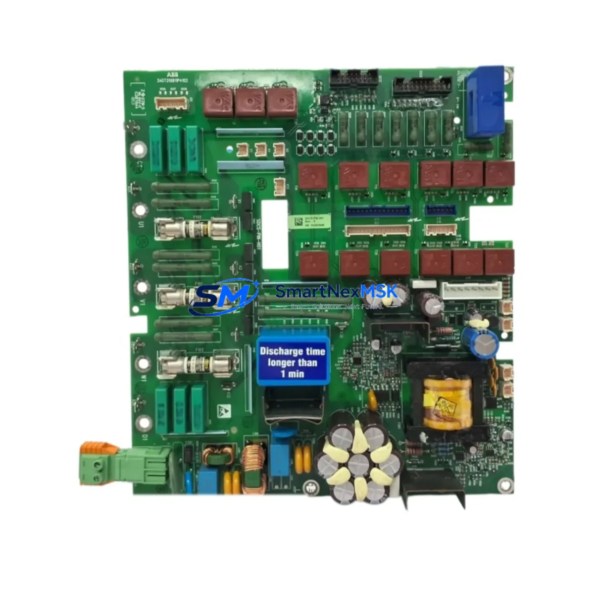
This board interfaces directly with the DCS800 drive’s power section, managing the critical signal routing between the control electronics and the power bridge. Its role in the drive architecture makes it a high-priority spare for any facility operating DCS800 units in continuous production environments such as paper mills, metal processing lines, crane systems, extruders, and winding machines.
Upgrade Compatibility Table
| Parameter | Details |
|---|---|
| Compatible Drive Series | ABB DCS800 (all frame sizes) |
| Board Function | Power Interface / Signal Bridge between Control and Power Section |
| Mounting / Installation | Direct board-level replacement; matches original PCB footprint and connector layout |
| Communication Compatibility | Compatible with SDCS-CON-4 control board and DCS800 firmware architecture |
| Terminal / Connector Interface | Matches OEM terminal block layout; no rewiring required for standard installations |
| Replacement Recommendation | Suitable as 1:1 replacement for failed or end-of-life SDCS-PIN-H01 units |
| Commissioning Notes | Verify drive firmware version; re-run autotune sequence after board swap |
| Warranty | 12 Months from date of shipment |
Retrofit Planning for Existing Automation Systems
Successful retrofit of the SDCS-PIN-H01 begins well before the board arrives on site. Engineers should start by auditing the existing DCS800 drive cabinet to confirm the current firmware version loaded on the SDCS-CON-4 control board, as firmware compatibility directly affects how the new power interface board initializes during startup. In multi-drive systems where several DCS800 units share a common DC bus, it is equally important to verify that the SDCS-DSL-4 digital serial link board and any installed SDCS-FEX-2 field excitation boards are operating within specification, since a fault on the power interface can cascade across the bus if not isolated correctly.
Before removing the failed board, document all parameter settings using the DriveWindow Light software or the ACS-AP-I assistant control panel. This ensures that motor nameplate data, speed reference scaling, torque limits, and protection thresholds are preserved and can be reloaded after the swap. Pay particular attention to the field current controller parameters if the drive is operating a separately excited DC motor, as these values are stored in the SDCS-CON-4 and must be verified against the motor datasheet after reinstallation.
For cabinet-level integration, inspect the 24 VDC auxiliary power supply feeding the control electronics. A degraded power supply is a common root cause of repeated power interface board failures and should be tested or replaced as part of the retrofit. Similarly, check the fiber optic connections between the SDCS-PIN-H01 and the IGBT or thyristor gate driver boards, as contaminated or damaged fiber links can cause erratic firing pulses that damage the replacement board prematurely.
In systems where the DCS800 communicates upstream via a PROFIBUS-DP or Modbus RTU fieldbus, confirm that the SDCS-COM-8 or equivalent communication adapter is correctly addressed and that the PLC or DCS host — whether a Siemens S7-300, ABB AC500, or Allen-Bradley ControlLogix — has the correct GSD file or EDS file loaded. After the board swap, perform a full communication link test before re-enabling the drive from the SCADA or HMI system to avoid unexpected motor starts.
Where the DCS800 is integrated into a larger control cabinet alongside ABB ACS880 AC drives or third-party variable frequency drives sharing the same control backplane, ensure that the I/O wiring to the terminal blocks on the SDCS-PIN-H01 is re-terminated according to the original wiring diagram. Mislabeled or transposed signal wires are a frequent source of commissioning delays and can result in incorrect speed feedback or loss of enable signals.
Downtime Control During System Migration
Minimizing production downtime during a power interface board replacement requires a structured approach that begins with pre-staging the replacement SDCS-PIN-H01 and all associated tools before the maintenance window opens. Where possible, use a spare DCS800 drive of the same frame size as a bench test platform to verify that the replacement board powers up correctly and passes the drive’s internal self-test routine before it is installed in the production cabinet.
During the swap, follow a strict electrostatic discharge (ESD) protocol. The SDCS-PIN-H01 contains sensitive gate drive circuitry that can be damaged by static discharge during handling. Use an ESD wrist strap and anti-static mat, and store the board in its original packaging until the moment of installation.
Once the board is installed, perform a controlled startup sequence: apply auxiliary 24 VDC power first, confirm that the SDCS-CON-4 control board recognizes the new power interface without fault codes, then apply main AC supply in a no-load condition before reconnecting the motor. Use the drive’s built-in oscilloscope function or an external power analyzer to verify that the firing angle and current waveforms are symmetrical before returning the drive to automatic control from the PLC or DCS.
For critical production lines where even a brief interruption is unacceptable, consider maintaining a pre-configured hot-spare DCS800 drive with the SDCS-PIN-H01 already installed and parameters pre-loaded, allowing a complete drive swap in under 30 minutes rather than a board-level repair under time pressure.
Retrofit Support FAQ
Q: Is the SDCS-PIN-H01 a direct replacement for all DCS800 frame sizes?
A: The SDCS-PIN-H01 is compatible across the DCS800 series. However, always cross-reference the drive’s nameplate frame size and the original board part number before ordering to confirm the correct variant. Contact our technical team with your drive serial number for confirmation.
Q: Do I need to re-enter all drive parameters after replacing the board?
A: The SDCS-PIN-H01 does not store drive parameters — these reside on the SDCS-CON-4 control board. If the control board is intact, parameters are preserved. We recommend backing up parameters via DriveWindow Light before any board-level work as a precaution.
Q: What commissioning steps are required after installation?
A: After installation, clear any active fault codes, perform a drive identification run (autotune) to re-verify motor parameters, and test the drive at low speed under no-load conditions before returning to full production. Verify all fieldbus communication links and HMI status displays before releasing the drive to automatic control.
Q: What does the 12-month warranty cover?
A: All SDCS-PIN-H01 units supplied by SMARTNEXMSK carry a 12-month warranty from the date of shipment, covering manufacturing defects and functional failures under normal operating conditions. Each unit undergoes pre-shipment functional testing. Warranty claims are supported directly by our technical team at sales@smartnexmsk.com.
© 2026 SMARTNEXMSK. All rights reserved.
Original Source: https://smartnexmsk.com
Contact: sales@smartnexmsk.com | +86 18259474341


