ABB SNAT 602 TAC Retrofit-Ready Relay Output Module: Seamless Compatibility Upgrade for Legacy ACS600 & ACS800 Control Systems
The ABB SNAT 602 TAC is a relay output module engineered for direct integration into ABB ACS600 and ACS800 series variable speed drive systems. As legacy drive platforms approach end-of-life and original spare parts become increasingly scarce, the SNAT 602 TAC remains one of the most sought-after retrofit components for engineers tasked with maintaining continuous production in aging automation environments. Whether you are replacing a failed unit, upgrading a control cabinet, or migrating an entire drive line to a modernized architecture, the SNAT 602 TAC provides the electrical and mechanical compatibility required to restore system function with minimal downtime.
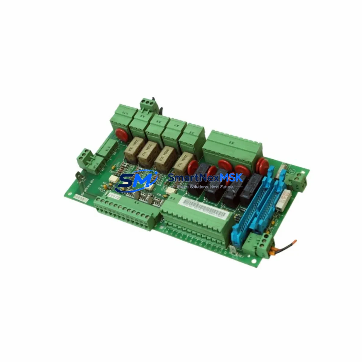
This module is designed to slot directly into the standard SNAT backplane used across the ACS600 and ACS800 drive families. Its relay output channels interface with external contactors, safety interlocks, motor protection relays, and supervisory control systems without requiring rewiring of existing terminal blocks. Engineers familiar with the SNAT 601 C or SNAT 603 EMC filter boards will recognize the consistent connector layout and DIN rail mounting geometry, which simplifies side-by-side installation in multi-drive control cabinets.
Upgrade Compatibility Table
| Parameter | Details |
|---|---|
| Compatible Drive Series | ABB ACS600, ACS800, DCS600, DCS800 |
| Module Type | Relay Output Module |
| Backplane Interface | SNAT standard backplane connector (direct plug-in) |
| Output Channels | Relay outputs for external contactor and interlock wiring |
| Installation Requirement | No rewiring required when replacing same-series SNAT module |
| Communication Compatibility | Compatible with DDCS fiber-optic communication links used in ACS600/ACS800 |
| Replacement Recommendation | Direct drop-in for failed or discontinued SNAT 602 TAC units |
| Commissioning Notes | Verify module address DIP switch settings match original configuration before power-up |
| Origin | Germany (OEM manufactured) |
| Warranty | 12-Month Warranty — covers manufacturing defects and functional failure under normal operating conditions |
Retrofit Planning for Existing Automation Systems
Successful integration of the SNAT 602 TAC into an existing control system requires a structured pre-installation review. Before removing the failed module, engineers should document the current DIP switch address settings on the module face, photograph the terminal wiring on the relay output connector, and record the drive firmware version displayed on the ACS600 or ACS800 control panel. This baseline documentation prevents configuration errors during reinstallation and reduces the risk of extended downtime.
Power supply capacity is a critical verification point. The SNAT backplane draws regulated 24 VDC from the drive’s internal SNAT 800 power supply module. If the existing SNAT 800 shows signs of aging — intermittent output voltage, audible relay chatter, or thermal discoloration — it is advisable to replace it concurrently with the SNAT 602 TAC to avoid a secondary failure shortly after commissioning. Similarly, inspect the NAMC-11 or NAMC-51 main control board for corrosion on the fiber-optic DDCS ports, as degraded optical connectors can cause communication faults that are misdiagnosed as relay output module failures.
For systems using the RDCO-01 or RDCO-02 DDCS communication adapter to link the drive to a higher-level DCS or SCADA platform, confirm that the communication channel assignments in the drive parameters remain unchanged after module replacement. In ACS800 applications where the RMIO-11 or RMIO-12 I/O extension board provides additional digital inputs, verify that the relay output logic in the drive application program correctly maps to the SNAT 602 TAC channel addresses. Mismatched channel mapping is a common source of post-replacement commissioning delays.
Control cabinet upgrades that involve replacing multiple SNAT modules simultaneously should follow a phased approach. Replace and verify one module at a time, running a partial functional test after each installation before proceeding to the next. This method isolates faults and prevents a single wiring error from cascading across the entire drive system. Where the original control cabinet includes an NPBA-12 PROFIBUS adapter or an NIBA-01 InterBus adapter for fieldbus communication, ensure that the fieldbus master configuration reflects any changes to the drive’s I/O mapping introduced during the retrofit.
HMI screens connected to the drive via the CDP 312 control panel or a third-party operator terminal should be reviewed for alarm and status display logic that references relay output states. After replacing the SNAT 602 TAC, perform a full HMI functional walkthrough to confirm that run, fault, and ready status signals are displayed correctly. Programming cables such as the RUSB-02 USB-to-RS232 adapter are useful for connecting a laptop to the drive’s serial port for parameter backup and restoration during the retrofit process.
Downtime Control During System Migration
Minimizing production downtime during a relay output module replacement requires preparation before the maintenance window begins. A complete parameter backup of the ACS600 or ACS800 drive should be performed using the drive’s built-in parameter upload function or via the DriveWindow Light PC tool connected through the RUSB-02 programming cable. This backup preserves all application-specific settings, including relay output logic, speed references, PID tuning parameters, and fieldbus communication addresses, ensuring that the drive can be restored to its exact pre-failure configuration if the replacement module requires parameter re-entry.
During the physical swap, de-energize the drive and wait for the DC bus voltage to discharge below 50 VDC before opening the control cabinet. Use the drive’s built-in DC bus voltage indicator or a calibrated multimeter to confirm safe voltage levels. Remove the SNAT 602 TAC by releasing the backplane locking tab, slide the module out along the guide rails, and insert the replacement unit until the backplane connector seats fully. Restore the DIP switch address settings to match the documented original configuration before applying power.
After power-up, monitor the drive’s fault log for any new fault codes related to the relay output module. Clear historical faults from the log before running the first production cycle to establish a clean baseline for post-retrofit monitoring. If the drive is connected to a PLC via hardwired I/O rather than fieldbus, perform a point-to-point I/O verification test with the PLC in manual mode to confirm that each relay output channel activates the correct downstream device. This structured commissioning approach typically allows a single-module replacement to be completed within a two-to-four hour planned maintenance window, preserving the continuity of the surrounding control system.
Retrofit Support FAQ
Q1: Is the SNAT 602 TAC a direct replacement for the original module in my ACS600 or ACS800 drive?
Yes. The SNAT 602 TAC is a direct plug-in replacement for the same module designation in ACS600 and ACS800 series drives. The backplane connector, module address scheme, and relay output wiring terminals are identical to the original factory-installed unit. No hardware modifications are required for a like-for-like swap.
Q2: What commissioning steps are required after installing the replacement module?
After physical installation, verify that the DIP switch address settings on the new module match the original configuration. Power up the drive and check the fault log for any relay output-related fault codes. Perform a functional test of each relay output channel by commanding the drive through its normal operating sequence and confirming that downstream contactors, interlocks, and status signals respond correctly. If the drive uses DDCS fiber-optic communication, confirm that the communication link status indicators on the NAMC board show a healthy connection.
Q3: Can the SNAT 602 TAC be used in DCS600 or DCS800 DC drive applications?
The SNAT 602 TAC is primarily specified for ACS600 and ACS800 AC drive platforms. Compatibility with DCS600 and DCS800 DC drive systems depends on the specific backplane configuration of the drive cabinet. We recommend confirming the backplane type and module address range with your drive documentation before ordering for a DCS application. Our technical team can assist with compatibility verification prior to shipment.
Q4: What does the 12-month warranty cover, and what is the process for a warranty claim?
The 12-month warranty covers manufacturing defects and functional failures under normal operating conditions, including relay contact failure, backplane connector faults, and internal component failures not caused by external overvoltage, incorrect wiring, or physical damage. To initiate a warranty claim, contact our sales team with the order reference number, a description of the fault symptom, and the drive fault log data. Replacement or repair will be arranged promptly to minimize impact on your production schedule.
© 2026 SMARTNEXMSK. All rights reserved.
Original Source: https://smartnexmsk.com
Contact: sales@smartnexmsk.com | +86 18259474341


