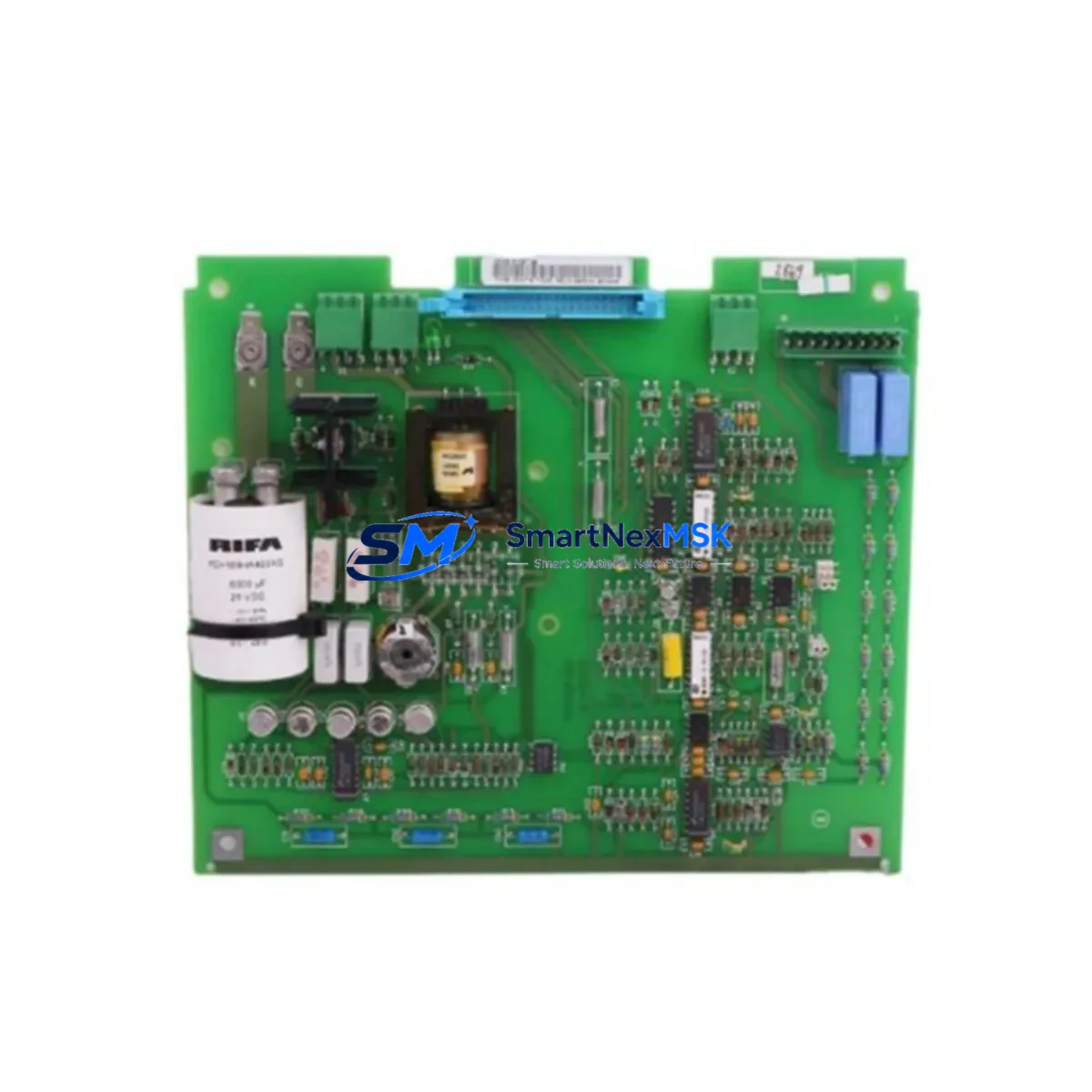
ABB SNAT617CHC Retrofit-Ready Gate Drive for ACS600 ACS800 Control Systems
The ABB SNAT617CHC is a gate drive control module engineered for seamless integration into legacy ABB ACS600 and ACS800 variable frequency drive platforms. As industrial facilities face increasing pressure to modernize aging automation infrastructure without full system replacement, the SNAT617CHC provides a proven, cost-effective path to restore drive performance, extend operational life, and maintain production continuity. Whether you are replacing a failed unit, upgrading a deteriorating control section, or executing a planned retrofit of an older drive cabinet, this module delivers the electrical and functional compatibility required for a smooth transition.
Upgrade Compatibility Table
| Parameter | Details |
|---|---|
| Compatible Drive Series | ABB ACS600, ACS800 |
| Module Function | Gate Drive Control – IGBT firing signal generation and protection |
| Installation Type | Direct board-level replacement; matches original mounting footprint |
| Connector Interface | Compatible with original ACS600/ACS800 backplane ribbon and terminal connectors |
| Communication Compatibility | Operates within existing DDCS fiber-optic communication architecture |
| Power Supply Requirement | Supplied via internal drive power bus; verify APOW-01 or equivalent auxiliary power module output before installation |
| Replacement Scope | Direct substitute for original SNAT617CHC; no firmware modification required in standard retrofit scenarios |
| Commissioning Requirement | Verify IGBT gate signal timing via DriveWindow or equivalent commissioning tool post-installation |
| Warranty | 12-Month Warranty – covers manufacturing defects and functional failure under normal operating conditions |
Retrofit Planning for Existing Automation Systems
Successful integration of the SNAT617CHC into an existing drive system begins well before the module arrives on site. Engineers and maintenance teams should conduct a thorough pre-retrofit audit of the drive cabinet to confirm that the APOW-01 auxiliary power supply module is delivering stable voltage within specification, as gate drive boards are sensitive to supply fluctuations. The AINT board (AINT-02 or AINT-14), which manages the DDCS fiber-optic communication links between the control section and the inverter, should also be inspected for connector integrity and fiber cleanliness before the new gate drive module is seated.
Terminal wiring on the RMIO-01 or RMIO-02 main I/O board must be documented and photographed prior to any disassembly. Analog and digital I/O assignments, speed reference wiring, and relay output connections are all routed through this board and must be preserved exactly during the swap. If the drive cabinet also houses an RDCO-01 or RDCO-02 DDCS communication adapter for fieldbus connectivity — such as PROFIBUS-DP or DeviceNet — verify that the fiber-optic loop addresses and baud rate settings are recorded before powering down.
For drives operating within a larger control architecture managed by an ABB AC500 PLC or a third-party controller via the RPBA-01 PROFIBUS adapter, confirm that the PLC program’s drive parameter references and fault word mappings remain valid after the module replacement. In some legacy installations, the RDNA-01 DeviceNet adapter or RCAN-01 CANopen module may be present; these communication modules are independent of the gate drive board and do not require reconfiguration, but their fiber connections to the AINT board should be re-seated as a precaution.
If the retrofit involves upgrading from an older ACS600 gate drive variant to the SNAT617CHC for an ACS800 application, pay particular attention to the IGBT module type and gate resistor values on the power stage. The SNAT617CHC is designed to interface with specific IGBT stack configurations; mismatched gate resistance can cause nuisance overcurrent trips or, in severe cases, IGBT damage. Consult the drive’s hardware manual and cross-reference the power module part number before proceeding.
Backplane slot addressing should also be verified. In multi-drive systems sharing a common ACS800-104 or ACS800-107 inverter cabinet, each drive section has a unique node address configured via DIP switches or parameter settings on the control board. Confirm that the replacement SNAT617CHC is installed in the correct slot and that node addressing is consistent with the existing system configuration to avoid communication conflicts on the DDCS ring.
Downtime Control During System Migration
Minimizing unplanned downtime is the primary operational concern when replacing a gate drive module in a live production environment. The recommended approach is to pre-stage the replacement SNAT617CHC by performing a bench-level power-on test using a controlled 24 VDC auxiliary supply before the scheduled maintenance window. This confirms the module is functional and eliminates the risk of installing a second faulty unit — a scenario that can double downtime and complicate fault diagnosis.
Before initiating the physical swap, use DriveWindow Light or the drive’s local control panel (CDP-312R or ACS-CP-C) to upload and save the complete parameter set from the existing drive. Store this backup on a laptop or USB device that will be present during commissioning. If the drive is connected to a SCADA or DCS system via the RDCO-01 DDCS adapter, notify the control room team to place the relevant control loop in manual mode to prevent process upsets during the transition.
Physical replacement of the SNAT617CHC typically takes 15–30 minutes for an experienced technician familiar with the ACS600/ACS800 board layout. After re-seating all connectors and fiber-optic cables, restore auxiliary power first and confirm that the control section initializes without fault codes before re-enabling the main DC bus. Run the drive in local control mode at low speed to verify gate signal integrity and motor response before returning the system to remote or automatic control. Document the commissioning results, including any parameter adjustments made during the process, and retain this record alongside the 12-month warranty documentation for future reference.
Retrofit Support FAQ
Q1: Is the SNAT617CHC a direct drop-in replacement for the original ABB gate drive board in ACS600 and ACS800 drives?
Yes. The SNAT617CHC is designed as a form-fit-function replacement for the original gate drive control module used in ABB ACS600 and ACS800 series drives. In standard retrofit scenarios, no firmware changes or parameter modifications are required. However, we recommend verifying the IGBT stack type and power module configuration against the drive’s hardware documentation before installation to ensure full compatibility.
Q2: What commissioning steps are required after installing the replacement module?
After physical installation, restore auxiliary power and confirm the control section boots without fault codes. Reload the saved parameter set using DriveWindow or the local control panel. Run the drive in local mode at reduced speed and verify gate signal timing, motor rotation direction, and current feedback. Check all DDCS fiber-optic communication links to the AINT board and confirm that any connected fieldbus adapters (RDCO-01, RPBA-01, etc.) are communicating correctly before returning the drive to automatic control.
Q3: How do I verify terminal wiring compatibility before replacing the gate drive board?
Document all terminal connections on the RMIO I/O board and any external wiring to the control section before disassembly. Photograph the wiring layout and record signal assignments for analog inputs, digital inputs, relay outputs, and the speed reference channel. The SNAT617CHC interfaces with the drive’s internal backplane and does not directly alter external terminal wiring, but confirming the existing wiring is correct before the swap prevents commissioning delays.
Q4: What does the 12-month warranty cover, and what is the process for a warranty claim?
The 12-month warranty covers manufacturing defects and functional failures under normal operating conditions from the date of shipment. It does not cover damage resulting from incorrect installation, overvoltage events, or operation outside the module’s rated specifications. To initiate a warranty claim, contact our sales team at sales@smartnexmsk.com with the order reference, a description of the fault, and any available fault codes or commissioning records. Replacement or repair will be arranged promptly to minimize your system downtime.
© 2026 SMARTNEXMSK. All rights reserved.
Original Source: https://smartnexmsk.com
Contact: sales@smartnexmsk.com | +86 18259474341


