ABB SPDS014 Retrofit-Ready Digital Input Module for AC500 Control Systems
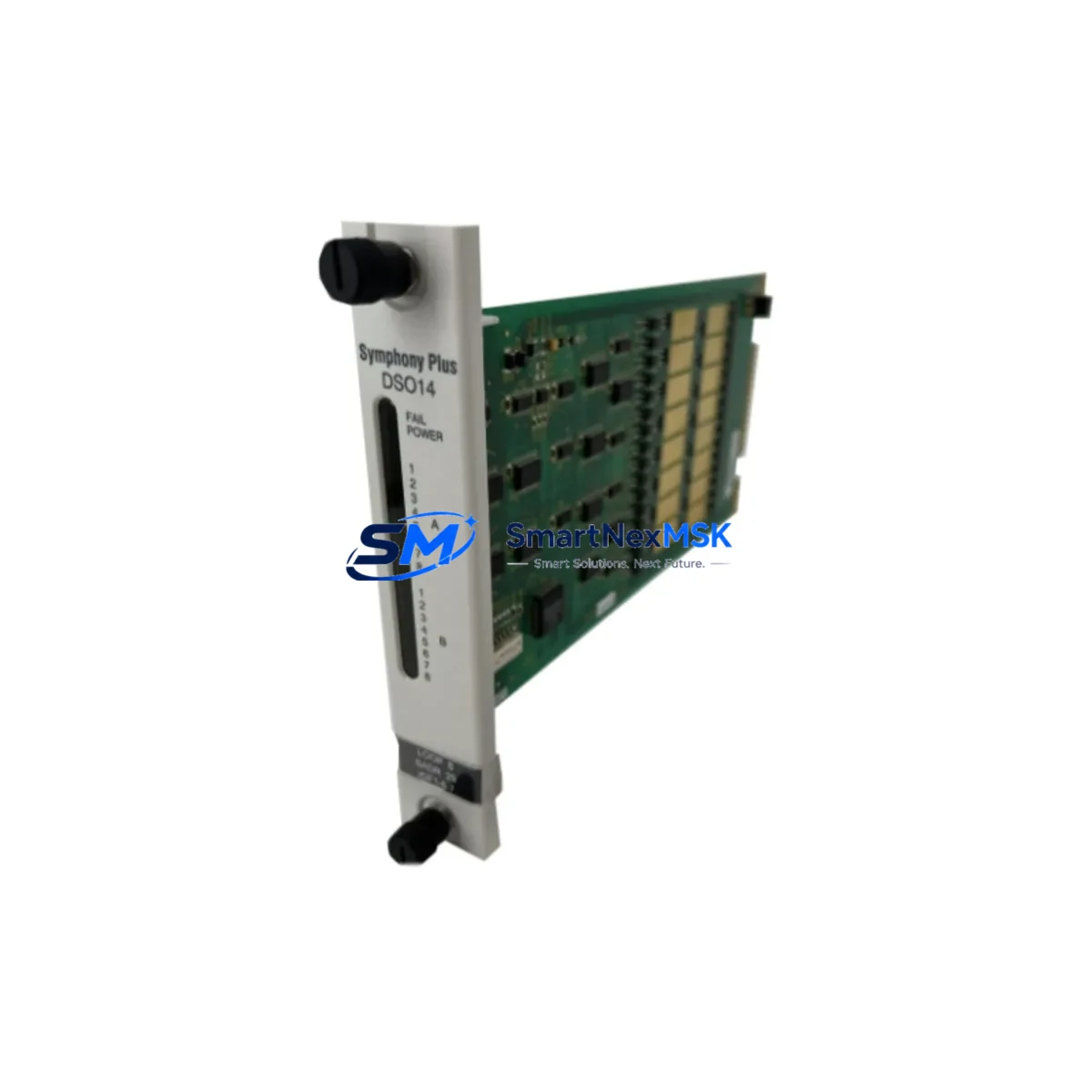
The ABB SPDS014 is a 14-channel, 24 VDC digital input module engineered for the ABB AC500 PLC platform. Designed as a direct retrofit replacement for aging or discontinued AC500 I/O modules, the SPDS014 delivers full signal compatibility, identical terminal mapping, and seamless backplane integration — making it the preferred choice for engineers managing legacy control system upgrades, production line modernization, and unplanned spare-part replacements.
Whether you are replacing a failed module in a running production cell, upgrading a control cabinet from an older AC500 generation, or migrating I/O capacity as part of a broader DCS or SCADA modernization project, the SPDS014 provides a verified drop-in solution that minimizes engineering rework and eliminates the need for program re-compilation in most standard retrofit scenarios.
Each unit is sourced from authorized supply channels, subjected to pre-shipment functional testing, and backed by a 12-month warranty. Stock is maintained in Xiamen for rapid dispatch to customers across Asia, Europe, and the Middle East.
Upgrade Compatibility Table
| Parameter | SPDS014 Specification | Retrofit Notes |
|---|---|---|
| Input Channels | 14 × 24 VDC Digital Inputs | Direct channel-for-channel replacement in AC500 racks |
| Backplane Interface | AC500 S500 I/O Bus | Compatible with PM571, PM581, PM591, PM595 CPUs |
| Terminal Wiring | Screw-type, 0.2–2.5 mm² | Existing field wiring reusable without modification |
| Communication | S500 local bus (PROFIBUS-DP compatible rack) | No protocol migration required for same-series swap |
| Module Address | Auto-assigned via rack slot position | Verify slot address in PS501 Control Builder before restart |
| Installation | DIN rail / AC500 S500 expansion rack | Compatible with TB521, TB541 terminal base units |
| Program Compatibility | IEC 61131-3 (ST, LD, FBD, IL, SFC) | Existing POU logic retained; no rewrite required |
| HMI Integration | CP600 / CP620 / CP635 panel compatible | HMI variable mapping unchanged for same I/O address |
| Warranty | 12 Months | Covers manufacturing defects; pre-shipment tested |
Retrofit Planning for Existing Automation Systems
A successful SPDS014 retrofit begins well before the module arrives on site. Engineers should first audit the existing AC500 S500 expansion rack to confirm available slot positions and verify that the TB521 or TB541 terminal base currently installed matches the SPDS014 footprint. In most AC500 installations, the terminal base remains in place during module replacement, which eliminates the need to disconnect field wiring — a significant advantage when working in live production environments.
Power budget verification is the next critical step. The SPDS014 draws its logic power from the S500 backplane bus, supplied by the AC500 power supply module (such as the PS501-ETH or PS560 series). Before inserting the replacement module, confirm that the rack’s total current draw — including all installed I/O modules, the CPU module (PM571, PM581, or PM591), and any communication modules such as the CI590-CS31-HA PROFIBUS coupler or CI501-PNIO PROFINET adapter — remains within the power supply’s rated output capacity.
For systems that include analog I/O alongside digital channels, the AX521 analog input module and AX522 analog output module should be reviewed for address conflicts if the rack configuration is being modified at the same time as the SPDS014 swap. Address assignment in AC500 is slot-based, so any change in rack layout requires a corresponding update in the PS501 Control Builder Plus hardware configuration before the program is downloaded to the CPU.
Where the retrofit involves migrating from an older AC31 or AC100 platform to the AC500 architecture, additional planning is required for communication protocol translation. Legacy AC31 systems using CS31 serial bus will require a CI590-CS31-HA coupler module to bridge existing field devices to the AC500 backplane. PROFIBUS DP networks can be retained using the CI840A or CI854A communication interface modules, preserving existing GSD-based device configurations and reducing re-engineering scope.
HMI panels connected to the system — including ABB CP600 operator panels or third-party SCADA terminals communicating via Modbus TCP or OPC-UA — should be tested against the updated I/O variable list after the module swap. In standard same-series replacements, variable addresses remain unchanged, and HMI screens require no modification. However, if the rack slot position of the SPDS014 differs from the original module, all affected I/O variable addresses must be updated in both the PLC program and the HMI project before commissioning.
Downtime Control During System Migration
Minimizing production downtime during a module replacement requires a structured pre-outage preparation protocol. Before the scheduled maintenance window, engineers should export a full backup of the current PLC program from PS501 Control Builder Plus, including the hardware configuration, all POUs, and the symbol table. This backup serves as the recovery baseline if the replacement module triggers unexpected behavior during first power-up.
Where the process allows, a hot-swap sequence can be executed on AC500 racks that support online module replacement. Confirm this capability with the specific CPU firmware version in use — PM591 and PM595 CPUs with firmware 3.x and above support online I/O replacement without a full CPU stop. For older PM571 installations, a controlled CPU stop is required, and the field team should coordinate with the process control room to place affected loops in manual mode before the outage begins.
During the physical swap, the TB521 or TB541 terminal base remains wired and in place. The SPDS014 module clips onto the terminal base without tools. After seating the module, verify the green RUN LED illuminates within 5 seconds of power restoration. If the module enters fault state (red LED), check the slot address assignment in the hardware configuration and confirm the firmware version is compatible with the installed CPU.
Post-replacement, perform a full I/O force test on all 14 channels before releasing the system to automatic control. Document the as-found and as-left states for each channel, and retain the pre-replacement program backup for a minimum of 90 days as part of the site’s change management record. The 12-month warranty covers any module failure attributable to manufacturing defects identified during this commissioning period.
Retrofit Support FAQ
Q1: Is the SPDS014 a direct drop-in replacement for older AC500 digital input modules?
Yes. The SPDS014 is designed for the AC500 S500 I/O platform and uses the same TB521/TB541 terminal base footprint as other S500 digital input modules. In same-series replacements, existing field wiring, terminal base, and rack slot can all be retained. No wiring modification is required in the majority of retrofit scenarios.
Q2: Will my existing PLC program need to be rewritten after installing the SPDS014?
Not in standard same-slot replacements. The SPDS014 occupies the same rack slot and inherits the same I/O address as the module it replaces. The existing IEC 61131-3 program logic, variable declarations, and HMI variable mappings remain valid. A program download is only required if the hardware configuration file is updated to reflect a firmware or module type change.
Q3: What pre-shipment testing is performed on each SPDS014 unit?
Each SPDS014 undergoes functional channel verification, backplane communication testing, and LED status confirmation prior to dispatch. Units are shipped with original packaging and documentation. A 12-month warranty is included, covering manufacturing defects. Customers requiring third-party inspection certificates or factory test reports should contact sales@smartnexmsk.com prior to order placement.
Q4: Can the SPDS014 be used in a PROFIBUS DP or PROFINET network?
The SPDS014 communicates via the AC500 S500 local I/O bus and does not connect directly to PROFIBUS DP or PROFINET. However, when installed in an AC500 rack equipped with a CI840A PROFIBUS master module or CI501-PNIO PROFINET adapter, the SPDS014’s I/O data is transparently mapped into the fieldbus network. No additional configuration of the SPDS014 itself is required for fieldbus integration.
© 2026 SMARTNEXMSK. All rights reserved.
Original Source: https://smartnexmsk.com
Contact: sales@smartnexmsk.com | +86 18259474341


