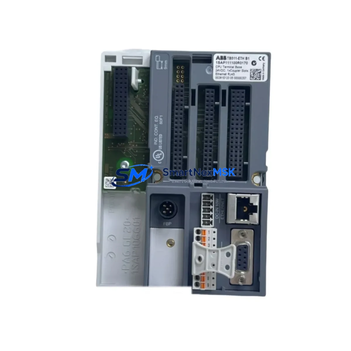
ABB TB511-ETH 1SAP111100R0170 Retrofit-Ready Terminal Base for AC500 Control Systems
The ABB TB511-ETH (1SAP111100R0170) is an Ethernet-enabled terminal base designed for the ABB AC500 PLC platform, providing a robust and reliable mounting and communication interface for AC500 CPU modules such as the PM571-ETH and PM581-ETH. As legacy AC500 installations age and original terminal bases reach end-of-life, the TB511-ETH serves as a direct retrofit-ready replacement that preserves existing wiring infrastructure, backplane addressing, and communication topology — minimizing engineering rework and unplanned downtime during system modernization.
Whether you are replacing a failed unit in a running production line, upgrading a control cabinet from an older AC500 V1 architecture to the current AC500 V2 standard, or migrating from a proprietary fieldbus to Ethernet-based protocols such as Modbus TCP or PROFINET IO, the TB511-ETH provides the physical and electrical foundation for a smooth transition. Its integrated Ethernet port eliminates the need for a separate CM572-DP or CM577-ETHIP communication module in many retrofit scenarios, reducing rack space consumption and simplifying the overall panel layout.
Before committing to a retrofit using the TB511-ETH, engineers should verify several critical compatibility parameters. First, confirm that the existing 24 VDC power supply — typically a CP604 or equivalent AC500-rated PSU — can sustain the combined current draw of the CPU module, I/O expansion modules, and any co-located DA501 or DA502 digital I/O modules mounted on the same rack. Second, inspect the terminal wiring on the existing base: the TB511-ETH uses the same 24-pin field wiring connector layout as earlier TB5xx-series bases, so existing field cables can typically be transferred without re-termination, but wire ferrule sizing and torque specifications should be re-verified per the ABB AC500 System Wiring Manual.
Backplane interface compatibility is another key checkpoint. The TB511-ETH is designed for the standard AC500 backplane bus and is compatible with TB5xx-series expansion racks using the TA526 or TA527 rack adapters. If the existing installation uses a TB521-ETH or TB541-ETH in a multi-rack configuration, verify that the inter-rack communication cable — typically a standard RJ45 Ethernet patch cable — is routed correctly and that IP addressing on the replacement CPU module is reconfigured to match the original node address before powering up.
Module address assignment must be confirmed in the Automation Builder or PS501 Control Builder Plus programming environment prior to commissioning. The TB511-ETH does not use DIP-switch-based addressing; instead, the CPU module’s IP address and slot configuration are defined in software. When replacing a failed terminal base in a live system, export the existing project from the original CPU using the programming cable (TK501 or USB-to-RS232 adapter) before powering down, and re-import it to the replacement unit after hardware installation. This preserves all POU logic, variable declarations, and task cycle configurations without manual re-entry.
HMI screen compatibility should also be reviewed. If the control system includes a CP600 series HMI panel or a third-party SCADA system communicating via Modbus TCP, the IP address change on the replacement CPU must be reflected in the HMI project’s communication driver settings. In most cases, assigning the same IP address to the replacement TB511-ETH-mounted CPU eliminates the need for HMI project modifications, allowing operators to resume normal supervisory control without retraining or screen redesign.
Communication link integrity should be validated after installation. Use the ABB AC500 Ethernet Diagnostics Tool or a standard network analyzer to confirm that the Modbus TCP or PROFINET IO connection between the TB511-ETH-hosted CPU and upstream SCADA, DCS, or MES systems is re-established within expected cycle times. Pay particular attention to PROFINET device naming if the replacement CPU is configured as a PROFINET IO controller — the device name must match the original configuration stored in the engineering tool to avoid communication faults on startup.
Field commissioning after a TB511-ETH retrofit typically follows a structured sequence: power-on self-test, I/O module recognition scan, communication link establishment, program download verification, and a supervised test run under manual override. All SMARTNEXMSK-supplied TB511-ETH units undergo pre-shipment functional testing including power-on verification, Ethernet port continuity check, and backplane connector inspection. Each unit ships with a 12-month warranty covering manufacturing defects and is sourced from verified supply channels to ensure authenticity and traceability.
Upgrade Compatibility Table
| Parameter | TB511-ETH (1SAP111100R0170) |
|---|---|
| Compatible CPU Modules | PM571-ETH, PM581-ETH, PM591-ETH, PM592-ETH |
| Communication Protocols | Modbus TCP, PROFINET IO, EtherNet/IP (via CM577-ETHIP) |
| Backplane Interface | AC500 standard backplane bus (TB5xx-series compatible) |
| Field Wiring Connector | 24-pin screw terminal, compatible with TB521/TB541 wiring layouts |
| Power Supply Requirement | 24 VDC (CP604 or equivalent AC500-rated PSU) |
| Rack Compatibility | TA526, TA527 rack adapters; AC500 standard DIN rail mounting |
| Programming Environment | Automation Builder, PS501 Control Builder Plus |
| Installation Type | Drop-in retrofit for TB5xx-series terminal bases |
| Retrofit Commissioning | IP address assignment, program re-download, I/O scan, comms verification |
| Warranty | 12 months — manufacturing defects, pre-shipment tested |
| Origin | Germany |
| Weight | 170 g |
Retrofit Planning for Existing Automation Systems
A successful TB511-ETH retrofit begins with a thorough audit of the existing control cabinet. In a typical AC500-based panel, the terminal base sits at the center of the hardware stack, interfacing the CPU module above with field wiring below and the backplane bus laterally. Before removal, document the positions of all co-installed modules: DA501 digital input modules, DA502 digital output modules, AX521 analog I/O modules, and any DC532 counter/frequency modules mounted in adjacent slots. Photograph the wiring harness and label each terminal block row to ensure accurate re-termination.
If the existing installation includes a CM572-DP PROFIBUS DP master module for legacy fieldbus communication, assess whether the retrofit scope includes protocol migration to Ethernet. The TB511-ETH’s integrated Ethernet port can replace the CM572-DP in many applications, but devices on the PROFIBUS segment — such as remote I/O stations, variable frequency drives, or third-party sensors — will require their own migration path or a PROFIBUS-to-Ethernet gateway. Plan this migration in parallel with the terminal base replacement to avoid creating a communication bottleneck after the CPU upgrade.
Power budget recalculation is mandatory when adding Ethernet-capable CPU modules to an existing rack. The CP604 power supply module provides up to 4 A at 24 VDC on the backplane bus; verify that the combined current draw of the new CPU, all I/O modules, and any co-located CM589-PNIO PROFINET IO controller modules does not exceed this limit. If the budget is tight, consider relocating lower-priority I/O modules to a secondary rack connected via the TA526 expansion adapter.
For installations where the original programming cable (TK501) is no longer available, a standard USB-to-RS232 adapter with the appropriate driver package can be used to establish a programming connection via the CPU’s serial port before the Ethernet link is configured. This is particularly important in brownfield sites where network infrastructure may not yet be extended to the control cabinet location.
Downtime Control During System Migration
Minimizing production downtime during a TB511-ETH retrofit requires careful pre-staging and a disciplined changeover sequence. Begin by pre-configuring the replacement CPU module on a bench setup: load the exported project, assign the correct IP address, verify I/O module recognition in simulation mode, and confirm that all program tasks compile and execute without errors. This bench validation step can reduce on-site commissioning time from several hours to under 30 minutes in most cases.
During the physical changeover, use the existing field wiring documentation to transfer terminal connections systematically — row by row, left to right — rather than disconnecting all wires simultaneously. This approach preserves wiring integrity and reduces the risk of mis-termination errors that could cause I/O faults on startup. If the control system includes a CP600 HMI panel displaying live process values, place the HMI in maintenance mode before powering down the CPU to prevent operator alarm fatigue during the transition.
After hardware installation and wiring transfer, perform a controlled power-up sequence: energize the 24 VDC supply first, confirm that the TB511-ETH’s status LEDs indicate normal backplane communication, then download the pre-validated program from the programming workstation. Execute a supervised test run with all field devices in manual override before returning the system to automatic control. Document the commissioning results — including I/O scan results, communication link status, and program cycle time measurements — and retain this record as part of the retrofit project file. All SMARTNEXMSK-supplied units include pre-shipment test documentation to support this commissioning record.
Retrofit Support FAQ
Q1: Is the TB511-ETH a direct drop-in replacement for the TB521-ETH or TB541-ETH?
The TB511-ETH shares the same field wiring connector layout and backplane bus interface as the TB521-ETH and TB541-ETH, making it physically compatible in most retrofit scenarios. However, the TB511-ETH is a single-slot base designed for standard AC500 CPU modules, while the TB541-ETH supports larger CPU variants. Confirm CPU module compatibility before ordering. SMARTNEXMSK’s technical team can assist with compatibility verification based on your existing hardware configuration.
Q2: Can I reuse my existing field wiring when replacing the terminal base?
In most cases, yes. The TB511-ETH uses the same 24-pin screw terminal connector layout as earlier TB5xx-series bases. Existing field cables can typically be transferred without re-termination, provided wire ferrule sizing and insulation ratings meet ABB’s specifications. Re-verify torque settings per the AC500 System Wiring Manual after re-termination.
Q3: What commissioning steps are required after installing the TB511-ETH?
After physical installation and wiring transfer, the key commissioning steps are: (1) assign the correct IP address to the CPU module via Automation Builder or PS501 Control Builder Plus; (2) download the pre-validated program; (3) perform an I/O module recognition scan; (4) verify Modbus TCP or PROFINET IO communication links; and (5) execute a supervised test run under manual override before returning to automatic control. Pre-shipment functional testing by SMARTNEXMSK reduces on-site commissioning risk.
Q4: What does the 12-month warranty cover, and what is the return process?
All TB511-ETH units supplied by SMARTNEXMSK carry a 12-month warranty covering manufacturing defects confirmed by pre-shipment functional testing. If a unit exhibits a defect within the warranty period, contact sales@smartnexmsk.com with your order reference and a description of the fault. SMARTNEXMSK will arrange a replacement or repair at no additional cost. Warranty does not cover damage resulting from incorrect installation, overvoltage, or unauthorized modification.
© 2026 SMARTNEXMSK. All rights reserved.
Original Source: https://smartnexmsk.com
Contact: sales@smartnexmsk.com | +86 18259474341


