ABB TK801V006 Retrofit-Ready ModuleBus Cable for AC500 & S500 Control Systems
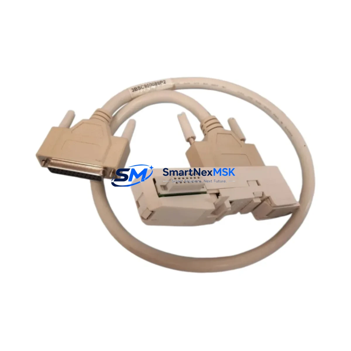
The ABB TK801V006 (catalog reference 3BSC950089R2) is a ModuleBus extension cable engineered for seamless integration into ABB AC500 and S500 distributed I/O architectures. As legacy control systems age and original cabling reaches end-of-life, the TK801V006 serves as a direct, drop-in replacement that restores full communication integrity between the CPU module and remote I/O stations — without requiring firmware changes, re-addressing, or panel redesign. Whether you are executing a planned retrofit, recovering from an unplanned cable failure, or upgrading an aging control cabinet, this cable delivers the electrical and mechanical compatibility your system demands.
In modernization projects where the AC500 PM573, PM583, or PM595 CPU is retained but the I/O infrastructure is being reorganized, the TK801V006 is frequently specified alongside the TB511-ETH or TB521-ETH communication interface modules to extend the ModuleBus segment to new rack positions. Engineers migrating from older S500 I/O racks — such as those using the DC532 digital input module or DA501 analog output module — rely on this cable to maintain the physical bus topology while reconfiguring the logical I/O map in the Control Builder Plus programming environment.
For control cabinets undergoing a full upgrade cycle, the TK801V006 is typically installed in conjunction with the TA521 expansion unit or the TU515 terminal unit, ensuring that the extended I/O segment maintains signal integrity across the full cable run. When the existing backplane or rack is being replaced as part of a panel rebuild, installers should verify that the ModuleBus connector orientation on the new rack matches the original pinout — a step that prevents polarity errors during initial power-up and commissioning.
Upgrade Compatibility Table
| Parameter | Details |
|---|---|
| Compatible CPU Series | ABB AC500 (PM571 / PM572 / PM573 / PM581 / PM582 / PM583 / PM591 / PM592 / PM595) |
| Compatible I/O Series | ABB S500 (DC532, DI524, DA501, AI523, DC522, DO526) |
| Replaces / Supersedes | TK801V006 (3BSC950089R2) — direct OEM equivalent |
| Connector Interface | ModuleBus 10-pin proprietary connector, keyed |
| Installation Requirement | No tools required; snap-fit locking mechanism; DIN rail compatible |
| Communication Protocol | ABB ModuleBus (proprietary serial backplane bus) |
| Protocol Migration Note | Not applicable for PROFIBUS or Modbus TCP migration — dedicated gateway modules required for protocol conversion |
| Retrofit Recommendation | Verify CPU firmware version supports extended I/O segment length before installation |
| Commissioning Checkpoint | Confirm module address DIP switch settings on each S500 I/O module after cable replacement |
| Warranty | 12 months from date of shipment — covers manufacturing defects and connector integrity |
Retrofit Planning for Existing Automation Systems
A successful retrofit begins well before the cable is physically installed. When planning a TK801V006 replacement in an operational AC500 system, the first step is to audit the existing ModuleBus segment: document the number of S500 I/O stations connected, the total cable run length, and the current module address assignments. In systems where the original TK801V006 has degraded due to mechanical stress or connector oxidation, intermittent communication faults will typically appear in the AC500 diagnostic buffer before a complete bus failure occurs — making early replacement a cost-effective strategy for downtime prevention.
During the physical replacement, engineers should also inspect the condition of the TB511 or TB521 bus terminal modules at each I/O station. These terminal units house the ModuleBus interface circuitry and are a common secondary failure point in aging S500 installations. If the terminal unit shows signs of connector wear or thermal discoloration, replacing it concurrently with the TK801V006 cable eliminates the risk of a repeat fault within the same maintenance window.
For projects involving I/O expansion — such as adding a DC532 digital input module or a DA501 analog output module to an existing rack — the TK801V006 provides the physical bus extension needed to reach the new rack position. In these cases, the system integrator must update the I/O configuration in ABB Control Builder Plus, assign the correct module address to the new station, and perform a full download to the PM573 or PM583 CPU before returning the system to automatic mode. If the project also involves upgrading the HMI — for example, migrating from a CP430 panel to a CP600 series touch panel — the HMI project must be updated to reflect any changes in I/O tag addresses that result from the rack reorganization.
Power supply capacity is another critical checkpoint. The AC500 system power supply — typically a PS501 or PS502 unit — must have sufficient residual capacity to support any additional I/O modules added during the retrofit. A load calculation should be performed before commissioning, accounting for the current draw of each DC532, DI524, or DA501 module in the expanded rack. Insufficient power supply headroom is a leading cause of intermittent faults in retrofitted systems and is often misdiagnosed as a cable or communication issue.
Downtime Control During System Migration
Minimizing production downtime during a ModuleBus cable replacement requires a structured approach to pre-staging, execution, and verification. Before the maintenance window opens, the existing AC500 program should be uploaded from the PM573 or PM583 CPU and archived — this preserves the current logic, I/O mapping, and retentive data values in the event that a rollback is required. The Control Builder Plus project file should be saved with a version-stamped filename and stored on a local engineering workstation, not solely on the CPU’s internal memory card.
During the cable swap, the CPU should be placed in STOP mode via the Control Builder Plus online interface or the front-panel RUN/STOP switch before disconnecting the ModuleBus cable. This prevents spurious output activations that could occur if the I/O modules lose bus communication while the CPU is still in RUN mode. After the TK801V006 is installed and the bus connectors are secured, the diagnostic LEDs on each S500 I/O station should be checked before the CPU is returned to RUN mode — a solid green BUS LED on each station confirms that the ModuleBus segment has been re-established correctly.
For systems where a cold restart is not acceptable — such as continuous process lines or safety-instrumented systems — a hot-swap strategy can be considered if the AC500 hardware configuration supports redundant I/O. In non-redundant installations, the recommended approach is to schedule the cable replacement during a planned production break, pre-stage the replacement TK801V006 cable with connectors pre-fitted, and limit the physical disconnection window to under five minutes. This approach, combined with a pre-verified spare cable from in-stock inventory, consistently achieves sub-ten-minute restoration times in field experience.
Retrofit Support FAQ
Q1: Is the TK801V006 a direct replacement for the original ABB 3BSC950089R2 cable, or are there wiring differences I need to account for?
The TK801V006 and 3BSC950089R2 are the same component — the latter is the full ABB catalog part number. The cable is a direct, pin-for-pin replacement with identical connector geometry and ModuleBus signal assignment. No rewiring, adapter, or termination change is required. Simply disconnect the original cable, install the TK801V006, and verify the BUS LED status on each connected S500 I/O station.
Q2: Will replacing the ModuleBus cable affect my existing AC500 program or require a new download to the CPU?
In most cases, a cable replacement alone does not require a program download. The AC500 CPU retains its program and I/O configuration in non-volatile memory. After the cable is replaced and the bus is re-established, the CPU will resume normal operation from its last saved state. A download is only required if the I/O configuration has changed — for example, if modules have been added, removed, or re-addressed during the same maintenance window.
Q3: How do I verify that the TK801V006 has been installed correctly before returning the system to production?
After installation, place the CPU in RUN mode and observe the diagnostic LEDs on each S500 I/O station. A solid green BUS LED on every station confirms successful ModuleBus communication. In Control Builder Plus, navigate to the online diagnostic view and confirm that all I/O modules are reporting their expected status. If any station shows a flashing or red BUS LED, check the connector seating at both ends of the TK801V006 and verify that the module address DIP switches have not been disturbed during installation.
Q4: What does the 12-month warranty cover, and what is the process for a warranty claim?
The 12-month warranty covers manufacturing defects in the cable assembly, including connector integrity, conductor continuity, and shielding performance. It does not cover damage resulting from incorrect installation, mechanical abuse, or use outside the specified operating environment. To initiate a warranty claim, contact our sales team with the order reference number and a description of the fault. We will arrange for a replacement unit to be dispatched from stock, typically within 24–48 hours of claim verification, to minimize any impact on your production schedule.
© 2026 SMARTNEXMSK. All rights reserved.
Original Source: https://smartnexmsk.com
Contact: sales@smartnexmsk.com | +86 18259474341


