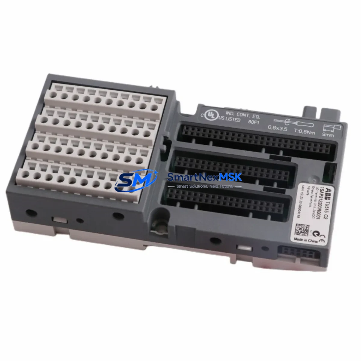
ABB TU515 1SAP212200R0001 Retrofit-Ready I/O Terminal for AC500 Control Systems
The ABB TU515 (1SAP212200R0001) is a compact, DIN rail-mounted I/O terminal unit engineered for the ABB AC500 PLC platform. Designed to serve as a direct retrofit replacement for aging or discontinued terminal base assemblies in legacy AC500 control cabinets, the TU515 enables engineers to modernize field wiring interfaces without redesigning the entire control architecture. Whether you are upgrading a production line, replacing a failed terminal unit, or migrating from an older AC500-S or AC500-eCo configuration, the TU515 provides a reliable, specification-matched solution that minimizes engineering rework and commissioning time.
In retrofit and modernization projects, the TU515 is typically paired with signal modules such as the SM560-S digital I/O module or the SM560-ECO compact I/O, both of which share the same AC500 backplane interface and terminal assignment conventions. When replacing terminal units in multi-rack configurations, engineers should also verify compatibility with the TB521-ETH communication module and the CI502-PNIO PROFINET I/O coupler, as these modules share the same rack bus and may require address reassignment after a terminal unit swap.
For installations that include legacy PROFIBUS DP field devices, the TU515 supports coexistence with the CI504-PBUS PROFIBUS master module, allowing engineers to maintain existing field device wiring while upgrading the terminal interface layer. This is particularly valuable in phased migration projects where the PROFIBUS network cannot be decommissioned in a single maintenance window.
Power supply compatibility is a critical verification step during any terminal unit replacement. The TU515 operates within the standard AC500 24 VDC system bus power envelope. Before installation, confirm that the existing PS501-PNIO or equivalent AC500 power supply module provides sufficient current headroom for the expanded I/O load, especially when adding new signal modules to the same rack. Insufficient power budget is one of the most common causes of intermittent faults during retrofit commissioning.
Backplane interface alignment must also be confirmed when inserting the TU515 into an existing rack. The module slot address is determined by physical position on the TA526 or TA527 rack assembly. If the replacement TU515 occupies a different slot than the original unit, the I/O module address in the Automation Builder project must be updated accordingly to prevent address conflicts and ensure correct PLC scan cycle mapping.
Upgrade Compatibility Table
| Parameter | Detail |
|---|---|
| Compatible PLC Platform | ABB AC500, AC500-S, AC500-eCo Series |
| Replaces / Supersedes | Legacy AC500 terminal base units; discontinued TU5xx variants |
| Mounting | DIN rail (TS 35), compatible with TA526 / TA527 rack assemblies |
| Bus Interface | AC500 internal backplane bus; compatible with CI502-PNIO, CI504-PBUS |
| Communication Compatibility | PROFIBUS DP, PROFINET I/O (via coupler modules) |
| Power Supply Requirement | 24 VDC system bus; verify PS501-PNIO or equivalent current budget |
| Terminal Wiring | Screw-type field terminals; verify existing cable cross-section and labeling before swap |
| Programming Environment | ABB Automation Builder (IEC 61131-3); no firmware change required |
| Slot Address Assignment | Physical slot position on rack; update Automation Builder project if slot changes |
| Retrofit Recommendation | Direct drop-in replacement; verify I/O module address and power budget |
| Commissioning Focus | Address mapping, terminal continuity check, PROFIBUS/PROFINET link verification |
| Warranty | 12 Months — covers manufacturing defects, functional failure under normal operating conditions |
Retrofit Planning for Existing Automation Systems
Successful retrofit of the TU515 into an operational AC500 control system requires a structured pre-installation review. Begin by documenting the existing terminal wiring layout using the original cabinet drawings. Each field cable connected to the legacy terminal unit must be labeled and photographed before disconnection to ensure accurate reconnection to the TU515 screw terminals. Pay particular attention to analog signal cables, which are sensitive to terminal sequence and shielding continuity.
Next, review the Automation Builder project file to identify all I/O variables mapped to the terminal unit being replaced. If the TU515 is installed in the same rack slot as the original unit, the hardware configuration in Automation Builder should require no changes. However, if the rack layout has been modified — for example, to accommodate an additional SM560-S digital input/output module or a new AI523 analog input module — the slot addresses must be updated and the project recompiled before download.
For systems that include an HMI panel such as the ABB CP635 or a third-party SCADA connected via OPC-UA or Modbus TCP, verify that all tag addresses referencing the replaced terminal unit remain valid after the retrofit. HMI screen objects linked to I/O tags on the TU515 rack should be tested in simulation mode before live commissioning to avoid unexpected alarm states during startup.
In multi-rack configurations using a TA526 expansion rack, confirm that the inter-rack communication cable between the CPU rack and the expansion rack is intact and that the expansion rack address DIP switches are correctly set. A misconfigured expansion rack address is a common source of I/O scan errors that can be mistakenly attributed to the replacement terminal unit.
Finally, if the system uses a TK501 programming cable or Ethernet-based programming connection, ensure that the Automation Builder project is backed up and version-controlled before any hardware changes are made. This protects the original program logic and allows rapid rollback if commissioning issues arise.
Downtime Control During System Migration
Minimizing production downtime during a terminal unit replacement requires careful pre-staging and a clear sequence of operations. The recommended approach is to pre-wire the new TU515 on a temporary DIN rail section outside the cabinet, verify terminal continuity with a multimeter, and confirm that all field cables are correctly labeled before the planned maintenance window begins.
During the maintenance window, follow this sequence: power down the affected rack section using the cabinet’s isolation switch, disconnect field cables from the legacy terminal unit in labeled groups, remove the old unit, install the TU515, reconnect field cables in sequence, and restore power. The entire physical swap can typically be completed in under 30 minutes for a single terminal unit, provided pre-staging is complete.
After power restoration, use the Automation Builder diagnostic view to confirm that all I/O modules on the rack are recognized and that no bus fault LEDs are active on the CI502-PNIO or CI504-PBUS coupler modules. Perform a forced I/O test on each channel to verify field device connectivity before releasing the system to automatic control mode. Document the commissioning results and update the cabinet drawings to reflect the new terminal unit part number.
For critical processes where even a brief interruption is unacceptable, consider a hot-standby approach using a redundant AC500 CPU configuration with the CM589-PNIO redundancy module, which allows one CPU to maintain control while the terminal unit on the secondary rack is replaced.
Retrofit Support FAQ
Q1: Is the TU515 a direct drop-in replacement for older AC500 terminal base units?
In most AC500 rack configurations, yes. The TU515 uses the same DIN rail footprint and backplane connector as standard AC500 terminal bases. However, always verify the specific rack type (TA526 or TA527) and confirm that the signal module mounted on the terminal unit is compatible with the TU515 interface before ordering.
Q2: Do I need to modify my Automation Builder project after replacing the terminal unit?
If the TU515 is installed in the same rack slot as the original unit, no project changes are required. If the slot position changes, update the hardware configuration in Automation Builder, recompile, and download the updated project to the CPU before restarting the system.
Q3: How do I verify wiring compatibility before installation?
Compare the terminal assignment diagram of the TU515 with the existing cabinet wiring drawings. Check cable cross-sections against the TU515 terminal specifications (typically 0.2–2.5 mm² for screw terminals). Verify that shielded analog cables are grounded at the correct terminal point. A continuity test on each field cable before reconnection is strongly recommended.
Q4: What does the 12-month warranty cover?
The 12-month warranty covers manufacturing defects and functional failure under normal operating conditions from the date of shipment. It includes free replacement or repair of confirmed defective units. The warranty does not cover damage caused by incorrect installation, overvoltage, reverse polarity, or unauthorized modification. Pre-shipment functional testing is performed on all units before dispatch.
© 2026 SMARTNEXMSK. All rights reserved.
Original Source: https://smartnexmsk.com
Contact: sales@smartnexmsk.com | +86 18259474341


