ABB TU841 3BSE020848R1 Retrofit-Ready Termination Unit for AC 800M Control Systems
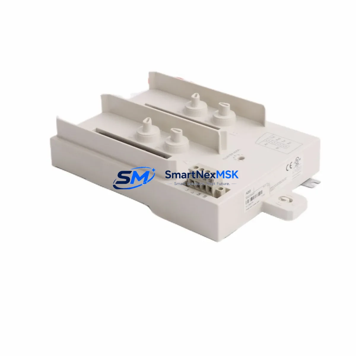
The ABB TU841 (3BSE020848R1) is a Redundancy Termination Unit engineered for the ABB AC 800M distributed control system platform, specifically designed to interface with the TB840 Profibus DP communication interface module. As legacy DCS installations age and OEM support windows close, the TU841 has become a critical retrofit component for engineers tasked with modernizing S800 I/O field cabinets without full system replacement.
SMARTNEXMSK maintains verified stock of the TU841 3BSE020848R1, sourced from authorized channels and subject to full functional testing prior to dispatch. Each unit ships with a 12-month warranty covering manufacturing defects and operational failures under normal industrial conditions.
Upgrade Compatibility Table
| Parameter | TU841 3BSE020848R1 Specification |
|---|---|
| Compatible Controller | ABB AC 800M (PM861, PM864, PM866 series) |
| Paired Communication Module | TB840 / TB840A Profibus DP Interface |
| Redundancy Support | Yes — dual-channel redundant Profibus DP |
| Backplane Interface | S800 I/O ModuleBus backplane (standard pitch) |
| Mounting | DIN rail / S800 I/O station baseplate |
| Communication Protocol | Profibus DP (IEC 61158) |
| Replacement Compatibility | Direct drop-in for TU841 units in existing S800 stations |
| Retrofit Recommendation | Verify TB840/TB840A firmware version before swap; no address re-configuration required for like-for-like replacement |
| Commissioning Note | Confirm Profibus DP node address on TB840 after installation; validate redundancy switchover in Control Builder M |
| Warranty | 12 Months — functional and manufacturing defect coverage |
Retrofit Planning for Existing Automation Systems
When planning a retrofit around the TU841 3BSE020848R1, the scope of work typically extends beyond the termination unit itself. In most AC 800M installations, the TU841 sits within an S800 I/O station alongside a range of signal modules — including AI810 analog input modules, AO810 analog output modules, DI810 digital input modules, and DO810 digital output modules — all mounted on a shared TB807 or TB820 baseplate. Engineers should audit the full station before ordering replacement parts, as aging baseplates and worn connector pins are a common source of intermittent faults that are often misdiagnosed as module failures.
The TU841 interfaces directly with the TB840 Profibus DP communication module, which connects the S800 I/O station to the AC 800M controller via the ModuleBus. In redundant configurations, a second TB840A is installed alongside the primary, and the TU841 provides the physical termination and switching logic for the redundant Profibus DP link. Before replacing the TU841, verify that the PM864 or PM866 controller module firmware is current, as older firmware versions may not correctly re-initialize the redundancy handshake after a cold swap.
Power supply integrity is a prerequisite for any S800 I/O retrofit. The SD821 or SD822 power supply module feeding the I/O station must be confirmed within its rated load capacity before adding or replacing modules. Overloaded power rails are a leading cause of unexplained module resets during commissioning. If the existing power supply is near its limit, plan for an SD823 supplementary power supply in parallel before proceeding with the TU841 swap.
For sites migrating from older Profibus DP segment topologies, the TU841 replacement is also an opportunity to audit the physical bus termination resistors at each end of the Profibus segment. Incorrect or missing termination is a frequent cause of communication instability after module replacement. Confirm that the Profibus DP segment is properly terminated at both ends and that the cable shielding is grounded at a single point to avoid ground loops.
HMI integration should be validated as part of the retrofit sign-off. If the plant uses an ABB Panel 800 operator terminal or a third-party SCADA connected via OPC to the AC 800M, confirm that all I/O tags mapped through the replaced S800 station are correctly resolved after the TU841 swap. In some cases, a forced download of the Control Builder M application to the PM8xx controller is required to re-establish tag bindings after a redundancy module replacement. Programming cable connectivity via the SC510 service port cable should be confirmed on-site before initiating any download.
Downtime Control During System Migration
Minimizing unplanned downtime is the primary concern for any live-system retrofit involving the TU841 3BSE020848R1. The recommended approach is a hot-standby swap procedure: with the redundant Profibus DP link active on the TB840A secondary channel, the primary TB840 and its associated TU841 can be de-energized and replaced without interrupting field I/O communication. This procedure requires that the redundancy switchover has been validated in advance using the Control Builder M diagnostic tools — specifically the redundancy status view — to confirm that the secondary channel is fully synchronized before initiating the swap.
Prior to any physical intervention, export a full backup of the AC 800M application from Control Builder M, including all hardware configuration files and Profibus DP GSD device definitions. This backup serves as the recovery baseline if the replacement TU841 triggers an unexpected configuration mismatch. Store the backup on an isolated engineering workstation, not on the controller’s own memory card, to ensure it remains accessible if the controller itself requires a cold restart.
After installing the replacement TU841, perform a Profibus DP live-list scan from the TB840 diagnostic interface to confirm that all slave devices — including remote I/O stations, variable frequency drives, and intelligent field devices — are visible on the bus before releasing the system back to automatic control. Document the pre- and post-swap live-list results as part of the site modification record. This documentation is also required to validate the 12-month warranty coverage in the event of a subsequent claim.
For sites without a redundant Profibus DP configuration, the swap window must be coordinated with the production schedule. A typical like-for-like TU841 replacement on a non-redundant station requires approximately 15–30 minutes of controlled I/O downtime, assuming the replacement unit has been pre-tested and the engineering workstation with Control Builder M is on-site and connected to the controller via the SC510 service port cable or Ethernet service interface.
Retrofit Support FAQ
Q1: Is the TU841 3BSE020848R1 a direct drop-in replacement for an existing TU841 in my S800 I/O station?
Yes. The TU841 3BSE020848R1 is the standard catalog part number for the TU841 Redundancy Termination Unit. It is a direct mechanical and electrical replacement for any TU841 currently installed in an S800 I/O station paired with a TB840 or TB840A Profibus DP module. No address reconfiguration or hardware modification is required for a like-for-like swap.
Q2: What commissioning steps are required after installing the replacement TU841?
After physical installation, reconnect the Profibus DP cables to the TB840/TB840A in the correct channel order (primary on Channel A, secondary on Channel B for redundant configurations). Power up the I/O station and observe the TB840 status LEDs — a solid green RUN indicator confirms successful Profibus DP initialization. Validate the redundancy switchover from Control Builder M before returning the station to automatic control. Log all commissioning steps for warranty and site modification records.
Q3: How do I verify wiring compatibility between my existing cabinet and the replacement TU841?
The TU841 does not have direct field wiring connections — it is a backplane-mounted termination unit that interfaces between the TB840 communication module and the S800 I/O station ModuleBus. Field wiring connects to the individual S800 signal modules (AI810, AO810, DI810, DO810, etc.) via their respective terminal units. Confirm that the S800 baseplate connector and ModuleBus backplane are in good condition before installing the replacement TU841, as damaged backplane connectors can cause intermittent faults that are not attributable to the TU841 itself.
Q4: What does the 12-month warranty cover, and what is the claims process?
The 12-month warranty covers manufacturing defects and functional failures under normal industrial operating conditions. It does not cover damage resulting from incorrect installation, overvoltage events, or physical mishandling. To initiate a warranty claim, contact SMARTNEXMSK with the original order reference, a description of the fault symptom, and the commissioning record. Units must be returned in original packaging with the fault clearly documented. Replacement or repair will be completed within the agreed lead time specified at the time of claim.
© 2026 SMARTNEXMSK. All rights reserved.
Original Source: https://smartnexmsk.com
Contact: sales@smartnexmsk.com | +86 18259474341


