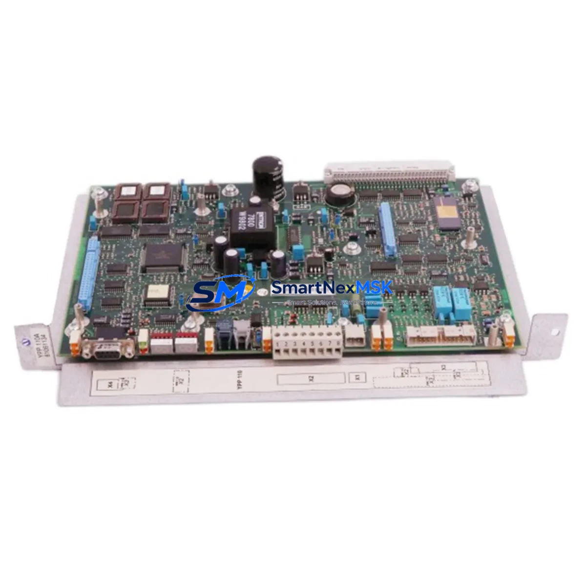
ABB YPP110A 3ASD573001A1 Retrofit-Ready Main Processor for ACS800 & DCS800 Control Systems
The ABB YPP110A (3ASD573001A1) is the main processor board engineered for the ACS800 and DCS800 series variable-speed drive platforms. As legacy drive fleets age and OEM support windows close, this module has become the cornerstone component in thousands of retrofit projects across steel mills, paper lines, marine propulsion systems, and process automation plants worldwide. Whether you are replacing a failed board, upgrading a discontinued control card, or modernizing an entire drive cabinet, the YPP110A delivers a verified drop-in upgrade path that preserves your existing wiring, parameter sets, and DDCS fiber-optic communication topology.
Upgrade Compatibility Table
| Attribute | Details |
|---|---|
| Compatible Drive Series | ACS800 (single & multi-drive), DCS800 DC Drive |
| Replaces / Supersedes | YPP110A Rev A–D, 3ASD573001A1, earlier YPPC-xx processor variants |
| Backplane Interface | Standard ACS800 / DCS800 control board slot; no mechanical adapter required |
| Communication Compatibility | DDCS fiber-optic (NAMC, RDCO), PROFIBUS-DP via RPBA-01, Modbus via RMBA-01, DeviceNet via RDNA-01 |
| Firmware Compatibility | Compatible with ACS800 standard application program and DCS800 firmware; parameter backup recommended before swap |
| Installation Requirement | ESD precautions; power-down sequence per ACS800/DCS800 hardware manual; no re-wiring of I/O terminals required for direct replacement |
| Retrofit Recommendation | Perform full parameter upload via DriveWindow or DriveStudio before removal; restore after installation |
| Commissioning Focus | Verify DDCS node address, check RDCO-02 fiber link integrity, confirm AI/AO scaling, run ID Run if motor data changed |
| Warranty | 12-Month Warranty — covers manufacturing defects and functional failure under normal operating conditions |
Retrofit Planning for Existing Automation Systems
A successful YPP110A retrofit begins well before the module arrives on site. Engineers managing aging ACS800 or DCS800 installations typically start by auditing the full drive cabinet: confirming the RMIO-11C or RMIO-02C I/O board revision, checking whether the RDCO-02 DDCS communication option board is still serviceable, and verifying that the NAMC-11 or NAMC-51 multi-drive controller firmware is compatible with the replacement processor. In multi-drive configurations, the APBU-44C branching unit and its fiber connections to each inverter module must be mapped before any board swap begins.
For DC drive applications on the DCS800 platform, the retrofit scope often extends to the SDCS-CON-4 control board and associated SDCS-PIN-4 power interface board. Technicians should document all field bus node addresses — particularly if the drive communicates over PROFIBUS-DP via an RPBA-01 adapter — since node IDs are stored in the processor and must be re-entered after replacement. Where Modbus RTU is used via an RMBA-01 option module, baud rate and parity settings should be recorded from the existing drive’s parameter list (Group 52) before shutdown.
Panel builders and system integrators upgrading older control cabinets frequently pair the YPP110A replacement with a simultaneous refresh of the AINT-02 or AINT-14 inverter control interface boards, taking advantage of the planned downtime window to address multiple aging components in a single outage. HMI screens built on ABB Panel Builder or third-party SCADA systems referencing ACS800 drive parameters via PROFIBUS or Modbus should be validated against the new processor’s parameter map — particularly Groups 01, 10, 13, and 99 — to confirm that all signal tags remain correctly mapped after the swap.
Programming cable access via the DDCS port or the front-panel RS-232 service port (using DriveWindow Light) allows technicians to perform a live parameter comparison between the backed-up dataset and the restored configuration, catching any discrepancies in speed reference scaling, torque limits, or fault response settings before the drive is returned to service.
Downtime Control During System Migration
Minimizing unplanned downtime is the primary concern for any production facility undertaking a drive processor replacement. The recommended approach is to pre-configure the replacement YPP110A off-line using a bench test setup — connecting a laptop running DriveStudio to the module via the DDCS service port, loading the backed-up parameter file, and verifying firmware version compatibility — before the scheduled maintenance window opens.
On the day of the swap, follow the ACS800 or DCS800 hardware manual power-down sequence: disable the drive enable signal, open the main contactor, wait for the DC bus to discharge below 50 V (confirmed via the drive’s DC bus voltage display or a calibrated multimeter), then remove the processor board. The YPP110A seats into the same control board slot without mechanical modification. After seating, restore the parameter file, confirm the DDCS node address, and perform a short no-load test run before reconnecting the process load.
For critical continuous-process applications — such as paper machine drives or compressor controls — a cold-standby strategy is advisable: keep a pre-configured spare YPP110A on the shelf with the parameter file already loaded, so that mean time to repair (MTTR) is reduced to under 30 minutes. Our in-stock inventory and same-day dispatch capability support this strategy directly, with units available for immediate shipment to minimize production impact.
Retrofit Support FAQ
Q1: Is the YPP110A 3ASD573001A1 a direct drop-in replacement for all ACS800 processor board variants?
A: The YPP110A is compatible with the standard ACS800 single-drive and multi-drive control board slot. It supersedes earlier YPPC-xx variants. Always verify the hardware revision of your existing board against the ABB ACS800 hardware manual (3AFE64527592) before ordering. For DCS800 applications, confirm the SDCS-CON-4 interface compatibility.
Q2: Do I need to re-enter all drive parameters after replacing the processor board?
A: Yes. The YPP110A does not retain parameters from the previous board. A full parameter backup using DriveWindow or DriveStudio must be performed before removal. After installation, restore the parameter file and verify critical groups (motor data Group 99, speed control Group 23, and fieldbus settings Group 51/52) before running the drive.
Q3: What commissioning steps are required after installation?
A: After parameter restore, verify the DDCS fiber-optic link status (RDCO-02 LED indicators), confirm the PROFIBUS or Modbus node address, check analog input/output scaling, and perform a no-load test run. If motor data was changed or is uncertain, execute an ID Run (parameter 99.10) to allow the drive to self-identify motor characteristics.
Q4: What does the 12-month warranty cover, and how is it handled?
A: The 12-month warranty covers manufacturing defects and functional failure under normal operating conditions from the date of shipment. Each unit undergoes functional testing prior to dispatch. In the event of a warranty claim, contact our technical team with the order reference and fault description; we will arrange replacement or repair with priority handling to minimize your downtime.
© 2026 SMARTNEXMSK. All rights reserved.
Original Source: https://smartnexmsk.com
Contact: sales@smartnexmsk.com | +86 18259474341


