ABB YPQ110A 3ASD573001A5 Retrofit-Ready I/O Module for ULMA Control Systems
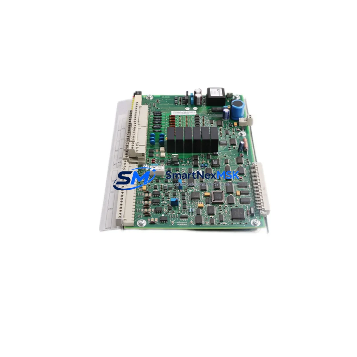
The ABB YPQ110A (part number 3ASD573001A5) is a high-reliability I/O module engineered for the ABB ULMA distributed control platform. As legacy ULMA installations approach end-of-life and original spare parts become increasingly scarce, the YPQ110A remains one of the most sought-after retrofit components for engineers tasked with sustaining or modernizing existing control architectures. SMARTNEXMSK maintains verified stock of this module, fully tested and backed by a 12-month warranty, ready for immediate dispatch to minimize your plant downtime.
Whether you are replacing a failed unit on a running production line, upgrading a control cabinet as part of a phased modernization program, or sourcing backup inventory ahead of a scheduled shutdown, the YPQ110A 3ASD573001A5 delivers the electrical and functional compatibility your system demands. Each unit shipped by SMARTNEXMSK undergoes pre-shipment functional verification to confirm signal integrity, backplane communication, and module addressing before it leaves our facility.
Upgrade Compatibility Table
| Parameter | Details |
|---|---|
| Module Part Number | YPQ110A / 3ASD573001A5 |
| Platform Compatibility | ABB ULMA Distributed Control System |
| Backplane Interface | ULMA standard backplane bus; verify slot assignment against rack layout drawing |
| Installation Requirement | DIN-rail or rack-mount per ULMA cabinet specification; confirm power rail voltage (24 VDC typical) |
| Communication Compatibility | Native ULMA internal bus; confirm firmware revision matches controller baseline |
| Replacement Recommendation | Direct drop-in for failed or end-of-life YPQ110A units; no hardware modification required |
| Commissioning Focus | Module address configuration, I/O channel mapping, and loop check against existing P&ID |
| Warranty | 12 months from date of shipment — covers manufacturing defects and functional failure |
Retrofit Planning for Existing Automation Systems
A successful retrofit of the YPQ110A 3ASD573001A5 begins well before the module arrives on site. Engineers should pull the existing rack layout and confirm the precise slot position occupied by the outgoing module, since the ULMA backplane assigns logical addresses by slot. Mislabeled or undocumented racks are a common source of commissioning delays — cross-reference the hardware configuration in your ABB Composer or Control Builder engineering tool before proceeding.
Power budget verification is equally critical. The ULMA power supply module — often a YPP110A or equivalent unit installed in the same rack — must have sufficient headroom to support the YPQ110A’s current draw alongside all co-installed modules. If the rack is already near capacity, consider whether a supplementary power supply or load redistribution across a second rack is warranted before the replacement window opens.
Terminal wiring on the field side should be documented with photographs and a point-to-point wiring schedule before any module is removed. The YPQ110A connects to field instruments through a dedicated terminal block or marshalling cabinet; confirm that the terminal block model (such as a YPCT31BC or compatible ABB terminal assembly) is undamaged and that all field cables are correctly labeled. Where cable labeling is absent or illegible, invest time in re-labeling during the planned outage rather than relying on memory during a live restoration.
For sites running mixed-generation ULMA hardware — for example, combining older YPQ-series I/O modules with a newer AC800M controller via an S800 I/O interface — verify that the communication module (such as an AF100 fieldbus interface or CI854 PROFIBUS adapter) is configured to recognize the YPQ110A’s module type and I/O channel count. Mismatched module type declarations in the hardware configuration will cause the controller to flag a hardware fault even if the module is physically healthy.
HMI faceplates and alarm pages tied to the replaced I/O channels should be reviewed in the SCADA or DCS operator station. If the original module’s channel assignments are preserved exactly, no HMI changes are required. However, if channel re-mapping occurs during the retrofit — for example, when consolidating I/O from a decommissioned rack into a new YPFB110A or similar expansion module — update the HMI tag database and perform a full display check before returning the loop to automatic control.
Where the retrofit scope extends beyond a single module replacement to a broader control cabinet upgrade — for instance, replacing an aging ULMA rack with a modern AC500 PLC platform using a PM591 or PM595 CPU module — the YPQ110A may serve as a bridging component during a phased migration, keeping legacy field wiring active while the new control layer is commissioned in parallel. This approach is particularly effective in continuous-process industries where a full cutover shutdown is not operationally feasible.
Downtime Control During System Migration
Minimizing unplanned downtime during a ULMA I/O module replacement requires a structured pre-outage preparation protocol. Before the maintenance window begins, export a full backup of the controller program, hardware configuration, and HMI project from your engineering workstation. Store copies on both a local drive and a removable medium kept at the control room. This ensures that if an unexpected issue arises during commissioning — such as a firmware incompatibility or a corrupted hardware configuration file — you can restore the previous state without delay.
During the physical swap, keep the outgoing YPQ110A module intact and do not discard it until the replacement has been confirmed healthy in service. The original module may be needed for reference — for example, to read DIP switch or jumper settings that were not captured in the as-built documentation. Once the new module is seated and powered, use the ABB engineering tool to perform an online hardware scan and confirm that the controller recognizes the YPQ110A at the correct rack address.
Loop checks should be conducted channel by channel, with a field technician at the instrument end confirming signal response while the control room engineer monitors the live value in the operator station. For analog I/O channels, verify both the 4–20 mA signal range and the engineering unit scaling. For digital I/O, confirm both the energized and de-energized states. Document the results of each loop check in a commissioning record before releasing the loop to automatic control.
Where the process cannot tolerate even a brief interruption, consider using a hot-standby or redundant I/O strategy if the ULMA platform supports it, or coordinate with operations to place affected control loops in manual mode at the DCS operator station before the module is removed. Restoring loops to automatic control should be done sequentially, not simultaneously, to avoid process upsets caused by simultaneous setpoint tracking errors across multiple loops.
Retrofit Support FAQ
Q1: Is the YPQ110A 3ASD573001A5 a direct replacement for the original ABB ULMA I/O module, or are hardware modifications required?
The YPQ110A 3ASD573001A5 is designed as a direct drop-in replacement for the original module of the same part number within the ULMA platform. No hardware modifications to the rack, backplane, or field wiring are required, provided the slot position and module address configuration are preserved. Confirm the firmware revision compatibility with your controller baseline using the ABB hardware compatibility matrix before installation.
Q2: What commissioning steps are required after installing the replacement module?
After physical installation, perform an online hardware scan from the ABB engineering tool to confirm module recognition. Configure the module address to match the original slot assignment, then conduct a full channel-by-channel loop check against the existing I/O list. For analog channels, verify 4–20 mA signal range and engineering unit scaling. For digital channels, confirm both energized and de-energized state responses. Document all results before returning loops to automatic control.
Q3: How do I verify wiring compatibility between the YPQ110A and my existing field terminal blocks?
Refer to the ABB ULMA wiring diagram for the YPQ110A and compare it against your as-built terminal block schedule. The module connects to field instruments via a dedicated terminal assembly; confirm that the terminal block model installed in your cabinet matches the module’s connector specification. If the original terminal block is damaged or non-standard, a compatible ABB replacement terminal assembly should be sourced and installed during the same maintenance window to avoid a second outage.
Q4: What does the 12-month warranty cover, and what is the process for a warranty claim?
The 12-month warranty covers manufacturing defects and functional failure under normal operating conditions from the date of shipment. It does not cover damage caused by incorrect installation, overvoltage, environmental exposure beyond the module’s rated specifications, or unauthorized modification. To initiate a warranty claim, contact SMARTNEXMSK at sales@smartnexmsk.com with your order reference, a description of the fault, and any available diagnostic data from the ABB engineering tool. Our technical team will assess the claim and arrange for a replacement or repair within the warranty period.
© 2026 SMARTNEXMSK. All rights reserved.
Original Source: https://smartnexmsk.com
Contact: sales@smartnexmsk.com | +86 18259474341


