AI-Tek 70082-1000-021 Retrofit-Ready VR Speed Sensor for Legacy Control Systems
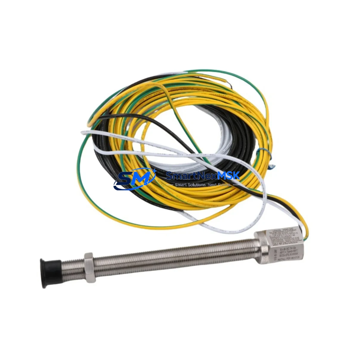
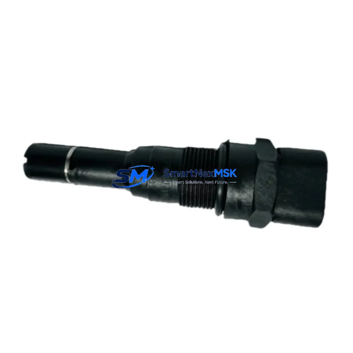
The AI-Tek 70082-1000-021 is a Variable Reluctance (VR) speed sensor engineered for precision rotational speed measurement in demanding industrial environments. As a retrofit-ready replacement component, it is widely deployed in legacy PLC and DCS control system upgrades, aging production line modernization projects, and control cabinet refurbishment programs where the original sensor has been discontinued or is no longer available through standard supply channels. Its passive magnetic sensing principle, robust housing, and industry-standard connector interface make it a reliable drop-in solution for engineers managing system continuity without full platform replacement.
When integrating the 70082-1000-021 into an existing automation architecture, engineers must verify several critical parameters before commissioning. Power supply compatibility is the first checkpoint — this sensor operates as a passive device generating its own signal voltage from the rotating target, so the receiving module’s input impedance and signal conditioning range must be confirmed against the sensor’s output characteristics. Terminal wiring must be mapped carefully: the two-wire output connects to the speed input card on the PLC rack, and polarity must be observed to avoid signal inversion. If the original installation used a three-wire active sensor, a signal converter or input module swap may be required before the 70082-1000-021 can be wired in directly.
Backplane interface and module addressing are equally important during retrofit planning. In Siemens S7-300 or S7-400 installations, for example, the speed input channel address in the hardware configuration (HW Config) must reflect the physical slot assignment of the receiving analog or counter module. Similarly, in Allen-Bradley ControlLogix or CompactLogix systems, the I/O tree tag structure must be updated if the input module type changes during the upgrade. Program logic referencing the old sensor’s tag or address block should be reviewed and updated in the PLC program before the new sensor is brought online.
HMI screen updates are often overlooked during sensor replacements. If the original sensor fed a speed display faceplate on a Siemens WinCC, Rockwell FactoryTalk View, or Schneider Electric Vijeo Citect SCADA system, the engineering team should verify that the tag binding, scaling factor, and engineering unit conversion remain valid after the swap. A mismatch between the new sensor’s output range and the HMI’s configured input scale can produce erroneous speed readings on the operator display without triggering any fault alarm.
Communication link integrity must also be confirmed. In distributed control architectures where the speed signal is transmitted over PROFIBUS DP, DeviceNet, or Modbus RTU to a remote I/O station, the field device replacement does not affect the network protocol itself — but the GSD file, EDS file, or Modbus register map should be reviewed to ensure the data type and register assignment remain consistent with the new sensor’s signal characteristics.
Upgrade Compatibility Table
| Parameter | Details |
|---|---|
| SKU / Part Number | 70082-1000-021 |
| Sensor Type | Variable Reluctance (VR) / Passive Magnetic |
| Output Signal | Sinusoidal AC voltage, amplitude proportional to speed |
| Connector Interface | Industry-standard 2-pin connector (verify mating connector on existing harness) |
| Target Compatibility | Ferromagnetic gear tooth, ring gear, or reluctor wheel |
| PLC Platform Compatibility | Siemens S7-300/400/1500, Allen-Bradley ControlLogix/CompactLogix, Schneider Modicon M340/M580 |
| DCS Compatibility | Emerson DeltaV, Honeywell Experion, ABB 800xA (via speed input module) |
| Installation Requirement | Verify air gap (0.5–1.5 mm typical), thread size, and mounting depth |
| Wiring Adaptation | Two-wire passive output; active-to-passive conversion may require input module change |
| Commissioning Note | Confirm signal amplitude at minimum operating speed before enabling speed interlocks |
| Warranty | 12 Months from date of shipment |
Retrofit Planning for Existing Automation Systems
A successful retrofit using the AI-Tek 70082-1000-021 begins with a thorough audit of the existing control cabinet. Engineers should document the current sensor’s wiring diagram, the receiving module’s input specification, and the PLC program’s speed calculation block before any hardware is removed. In many legacy installations, the speed sensor feeds directly into a Siemens FM 350-1 counter module or an Allen-Bradley 1756-HSC high-speed counter module, both of which are designed to accept VR sensor signals. If the existing counter module is also being replaced as part of a broader upgrade, the new module’s input filter settings and encoder interface configuration must be programmed before the sensor is connected.
For installations involving I/O expansion — for example, adding a new Siemens ET 200SP distributed I/O station or a Rockwell 1734 POINT I/O block to accommodate additional speed monitoring points — the 70082-1000-021 can be wired to the new I/O node’s speed or frequency input module. The PROFINET or EtherNet/IP network segment connecting the new I/O station to the main PLC rack must be commissioned and verified before the sensor signal is mapped into the control program.
Power supply capacity in the control cabinet should be assessed when adding new modules. A Siemens SITOP PSU100S or Phoenix Contact QUINT power supply unit rated for the expanded I/O load is recommended. If the cabinet also houses a Siemens SINAMICS G120 or Allen-Bradley PowerFlex 755 variable frequency drive that references the speed sensor signal for closed-loop control, the drive’s encoder feedback parameter set must be updated to reflect the new sensor’s pole count and signal type.
Programming cable access is required for final commissioning. A Siemens PC Adapter USB A2 or a Rockwell 1784-U2DHP USB-to-DH+ cable may be needed to connect the engineering workstation to the PLC for online monitoring and program download. During commissioning, the speed signal should be verified in the PLC’s online diagnostic view before the machine is returned to automatic mode.
Downtime Control During System Migration
Minimizing production downtime during a speed sensor replacement requires careful pre-staging and a structured changeover procedure. Before the planned maintenance window, the replacement 70082-1000-021 should be bench-tested using a signal simulator or a slow-rotating test rig to confirm output signal integrity. The PLC program backup should be saved to the engineering workstation and a memory card, and the HMI project archive should be exported before any hardware changes are made.
During the changeover, the original sensor should be removed only after the machine has been safely de-energized and locked out per LOTO procedures. The new sensor should be installed, air gap set, and wiring connected before power is restored. On first power-up, the speed signal should be monitored in the PLC’s online I/O diagnostic screen to confirm the sensor is generating a valid signal before any automatic control sequences are re-enabled. Speed interlock setpoints and alarm thresholds should be verified against the original commissioning records before the machine is returned to production.
For critical continuous-process applications where even brief shutdowns are costly, a parallel installation approach can be used: the new sensor is mounted alongside the original (if a second mounting port is available), wired to a spare input channel, and its signal validated in shadow mode before the control program is switched over to the new input. This approach eliminates the risk of an extended outage caused by unexpected commissioning issues and preserves the original control logic continuity throughout the transition.
Retrofit Support FAQ
Q1: Is the AI-Tek 70082-1000-021 a direct drop-in replacement for the original sensor?
In most cases, yes — provided the original sensor was also a two-wire passive VR type with the same connector and thread specification. If the original was an active Hall-effect sensor with a three-wire output and a DC supply, an input module change or signal conditioner will be required. Always compare the original sensor’s datasheet with the 70082-1000-021 specification before ordering.
Q2: What commissioning steps are required after installation?
After physical installation, verify the air gap between the sensor tip and the target wheel, confirm wiring polarity, and monitor the signal in the PLC’s online diagnostic view at low speed before enabling any speed-dependent interlocks or drive feedback loops. Update the HMI tag scaling if the new sensor’s output range differs from the original.
Q3: Can this sensor be used with both Siemens and Allen-Bradley PLC platforms?
Yes. The 70082-1000-021 generates a standard sinusoidal VR output that is compatible with the speed/frequency input modules available for Siemens S7-300/400/1500, Allen-Bradley ControlLogix/CompactLogix, and Schneider Modicon M340/M580 platforms, as well as most DCS speed input cards. Module-specific configuration parameters (filter frequency, input impedance, scaling) must be set correctly in the platform’s hardware configuration tool.
Q4: What does the 12-month warranty cover?
All units are shipped after outgoing quality inspection and carry a 12-month warranty from the date of shipment covering manufacturing defects and functional failures under normal operating conditions. Warranty claims are supported by our technical team at sales@smartnexmsk.com. Replacement or repair will be arranged promptly to minimize your production impact.
© 2026 SMARTNEXMSK. All rights reserved.
Original Source: https://smartnexmsk.com
Contact: sales@smartnexmsk.com | +86 18259474341