AI-Tek 70085-1010-001 Spare for 70085 Series Automation: Precision Speed Sensing for Uninterrupted Industrial Operation
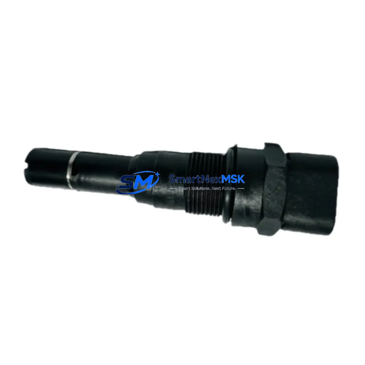
The AI-Tek 70085-1010-001 is an original variable reluctance speed sensor engineered for demanding industrial automation environments. Designed as a direct maintenance-ready spare for the AI-Tek 70085 Series, this sensor delivers reliable rotational speed feedback to PLC and DCS control systems, ensuring accurate process monitoring and rapid recovery from unplanned downtime. Whether you are managing a scheduled overhaul, responding to an emergency fault, or building a proactive spare parts inventory, the 70085-1010-001 is a critical component that maintenance and procurement engineers should have on hand.
Spare Maintenance Table
| Parameter | Specification |
|---|---|
| Part Number | 70085-1010-001 |
| Brand | AI-Tek Instruments |
| Series | 70085 Series |
| Type | Variable Reluctance Speed Sensor |
| Output Signal | Sinusoidal AC voltage (passive, no external power required) |
| Operating Temperature | -40°C to +150°C |
| Thread / Mounting | Standard threaded body; refer to OEM installation drawing |
| Connector Type | 2-pin industrial connector (series-standard) |
| Compatibility | AI-Tek 70085 Series; compatible with standard VR sensor inputs on Siemens, Allen-Bradley, Mitsubishi, and Omron PLC/DCS speed input modules |
| Application Environment | Rotating machinery, turbines, conveyors, motors, gearboxes, industrial drives |
| Maintenance Recommendation | Inspect air gap, connector integrity, and cable shielding at each planned maintenance interval |
| Origin | USA |
| Weight | 650 g (packaged) |
| Warranty | 12 Months — tested and verified before shipment |
Maintenance Planning for Continuous Operation
When replacing the AI-Tek 70085-1010-001 speed sensor in the field, a thorough inspection of the surrounding control circuit is essential to prevent repeat failures and ensure system stability. Maintenance engineers should treat this replacement as an opportunity to audit the entire speed measurement and control loop.
Begin by verifying the signal conditioning module or frequency-to-voltage converter that processes the sensor’s sinusoidal output — a degraded converter can mask a healthy sensor or damage a new one. Check the shielded sensor cable and connector assembly; corroded pins or damaged shielding are a leading cause of erratic speed readings and nuisance trips. Inspect the PLC speed input module (such as an Allen-Bradley 1756 HSC or Siemens S7-300 FM350 counter module) for correct threshold settings and input impedance compatibility with the 70085-1010-001’s passive output.
In the control cabinet, verify the 24 VDC or 120 VAC power supply rail feeding the associated control logic — voltage sag or ripple can cause false speed fault alarms even after a sensor swap. Inspect terminal blocks and DIN rail connections in the speed feedback circuit for loose terminations, which are a common source of intermittent faults in high-vibration environments. If the system uses a signal isolator or galvanic isolator between the sensor and the PLC input, confirm the isolator’s frequency response range covers the expected speed signal bandwidth.
For systems with an integrated overspeed protection relay (such as a Woodward 9907 or equivalent), recalibrate the trip setpoint after sensor replacement to confirm the new sensor’s output amplitude matches the relay’s detection threshold. Where a DCS historian or SCADA system logs speed trends, validate the engineering unit scaling after replacement to avoid false process alarms. If the machine uses a proximity switch or encoder as a redundant speed reference, cross-check both signals during commissioning to confirm agreement within tolerance.
Finally, review the motor drive or VFD speed feedback configuration if the sensor feeds a closed-loop drive system — incorrect feedback gain settings after a sensor change can cause instability or runaway conditions. Keeping a documented spare parts kit that includes the 70085-1010-001 sensor, a matched connector assembly, a spare signal cable, and a backup signal isolator will significantly reduce mean time to repair (MTTR) for speed-related faults.
Site Replacement Workflow
The AI-Tek 70085-1010-001 is a direct drop-in replacement for worn or failed units within the 70085 Series, and in many cases serves as a compatible substitute for legacy AI-Tek models that have reached end-of-life. To minimize downtime during replacement:
Step 1 — Isolation: De-energize the machine and lock out / tag out (LOTO) the drive system. Confirm zero speed on the control system display before approaching the sensor mounting location.
Step 2 — Air Gap Measurement: Before removing the old sensor, record the existing air gap between the sensor tip and the toothed wheel or gear. The 70085-1010-001 requires a precise air gap (typically 0.25–1.0 mm depending on gear tooth geometry) to produce a clean signal. Use a feeler gauge to set the new sensor to the same gap.
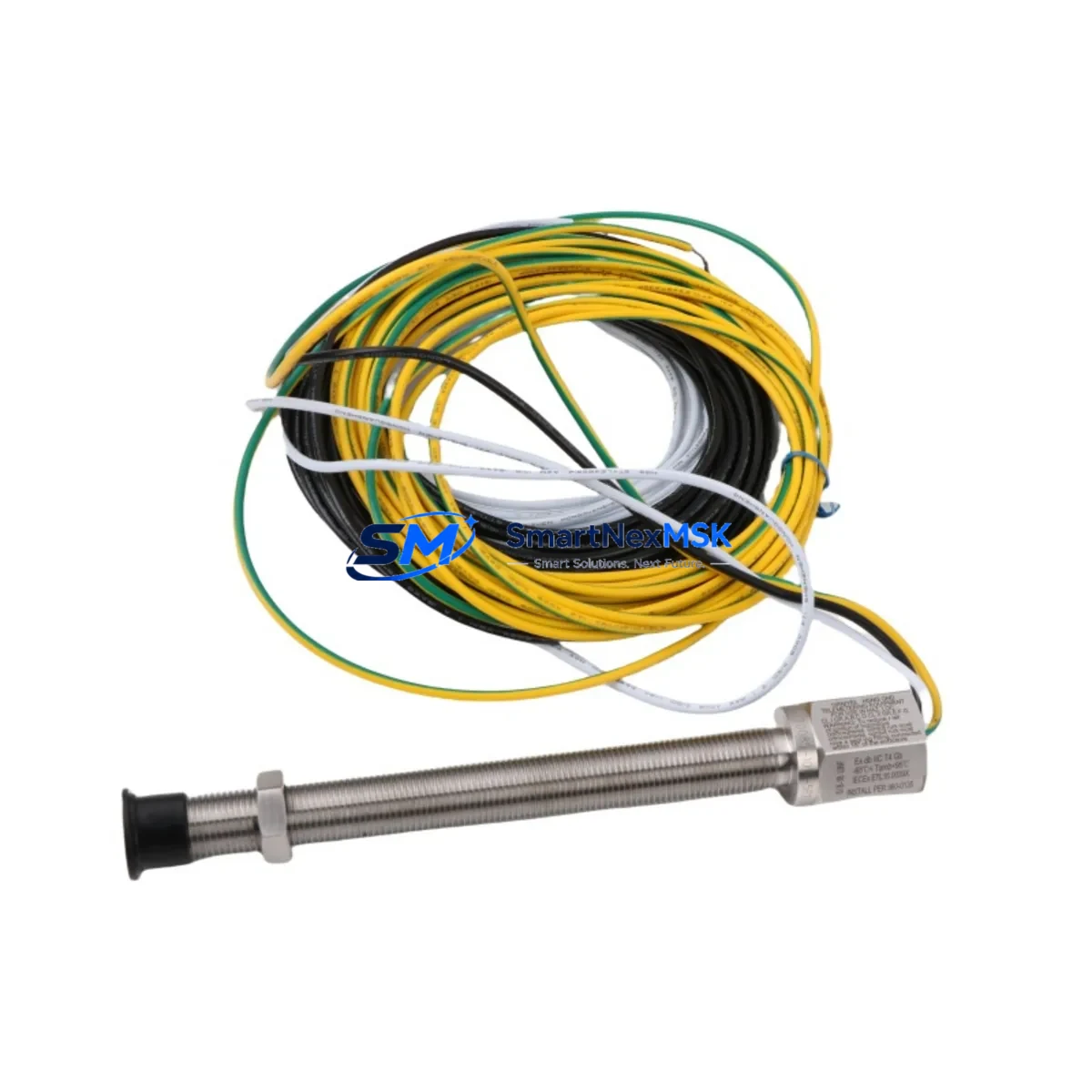
Step 3 — Connector and Cable Inspection: Clean the mating connector with contact cleaner. Inspect the cable for chafing, especially near vibrating machine members. Replace the cable if the outer jacket is cracked or the shield braid is exposed.
Step 4 — Installation and Torque: Thread the new 70085-1010-001 into the mounting boss by hand, then torque to the OEM specification. Over-torquing can crack the sensor body; under-torquing allows vibration-induced loosening.
Step 5 — Signal Verification: Re-energize and run the machine at a known reference speed. Use a multimeter or oscilloscope to confirm the sensor output frequency matches the expected value (frequency = speed × tooth count / 60). Verify the PLC or DCS is receiving a clean, stable speed value before returning the machine to production.
This systematic approach eliminates the most common causes of repeat sensor failures and ensures the replacement delivers the full service life expected from an original AI-Tek component.
Spare Parts Support FAQ
Q1: Is the AI-Tek 70085-1010-001 compatible with my existing 70085 Series mounting and wiring?
Yes. The 70085-1010-001 is designed as a direct replacement within the 70085 Series family, sharing the same threaded body dimensions, connector pinout, and passive sinusoidal output characteristics. No wiring modifications are required for like-for-like replacement. If you are substituting for an adjacent AI-Tek model number, please confirm the thread size and connector type before installation.
Q2: How is the unit tested before shipment?
Every 70085-1010-001 unit is bench-tested for coil continuity, insulation resistance, and output signal integrity prior to packaging. A test report is available upon request. Units are shipped in anti-static, padded packaging to prevent transit damage to the sensor tip and connector.
Q3: What is the recommended spare parts stocking strategy for this sensor?
For critical production lines, we recommend maintaining a minimum of two units on-site. Variable reluctance speed sensors in high-vibration or high-temperature environments typically require replacement every 2–5 years depending on duty cycle. Pairing the 70085-1010-001 with a spare signal cable assembly and a backup signal isolator provides a complete field-replaceable kit that covers the most common failure modes in a single maintenance event.
Q4: What warranty and after-sales support is provided?
All units carry a 12-month warranty covering manufacturing defects and premature failure under normal operating conditions. Our technical team provides pre-sale compatibility verification, installation guidance, and post-sale troubleshooting support. Long-term supply agreements are available for OEM integrators and MRO procurement teams requiring guaranteed stock availability.
© 2026 SMARTNEXMSK. All rights reserved.
Original Source: https://smartnexmsk.com
Contact: sales@smartnexmsk.com | +86 18259474341