AMAT 0100-20100 Retrofit-Ready Analog I/O PCB for Centura Control Systems
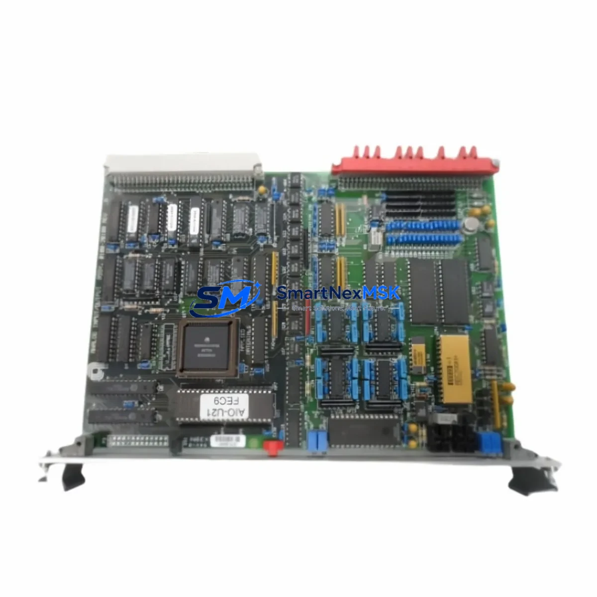
The AMAT 0100-20100 is an Analog I/O PCB Board engineered for Applied Materials Centura semiconductor process control platforms. As legacy Centura chambers age and original boards reach end-of-life, sourcing a verified, drop-in compatible replacement becomes critical to maintaining process uptime and yield stability. SMARTNEXMSK stocks the 0100-20100 as a retrofit-ready solution for facilities managing aging CVD, PVD, and etch tool fleets where the original Applied Materials supply chain has been discontinued or lead times are unacceptable.
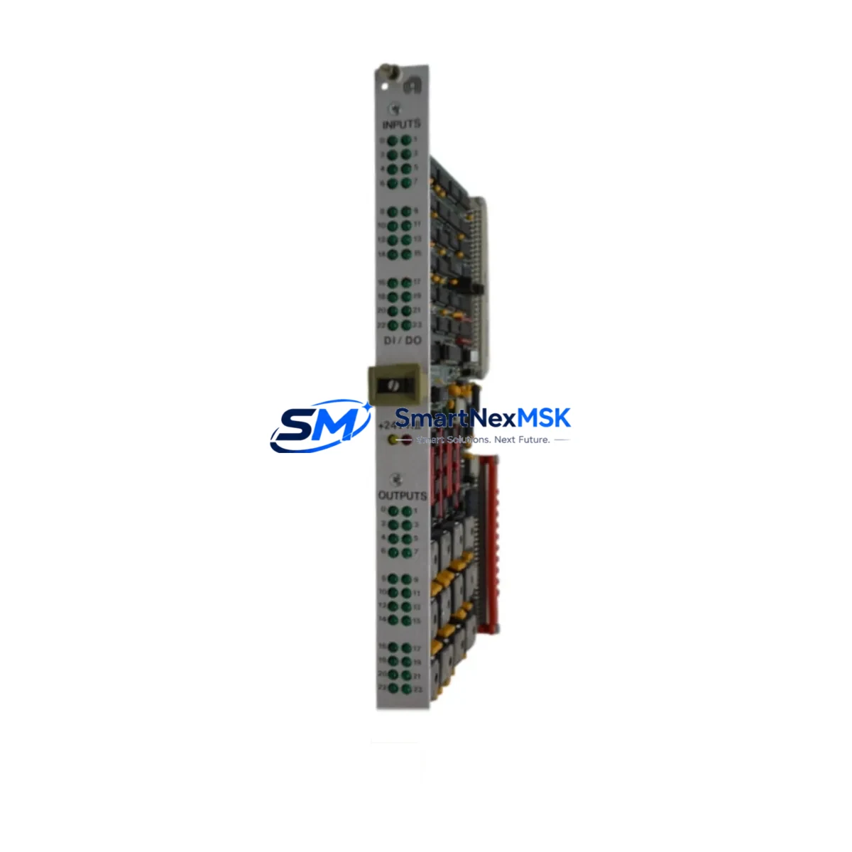
This board interfaces directly with the Centura mainframe backplane, handling analog signal conditioning for process parameter monitoring including chamber pressure, RF power feedback, gas flow analog outputs, and temperature loop inputs. It is fully compatible with the standard 19-inch Centura equipment front-end module (EFEM) rack architecture and requires no firmware modification when used as a direct replacement for the original 0100-20100 assembly.
Upgrade Compatibility Table
| Parameter | Details |
|---|---|
| Part Number | AMAT 0100-20100 |
| Function | Analog I/O Signal Conditioning PCB |
| Compatible Platform | Applied Materials Centura (CVD, PVD, Etch) |
| Backplane Interface | Standard Centura 19″ VME-style rack connector |
| Signal Type | Analog input/output (4–20 mA, 0–10 V) |
| Communication Compatibility | Compatible with Centura host controller I/O bus |
| Installation Requirement | Direct board swap; no rack modification required |
| Replacement Recommendation | Drop-in for original AMAT 0100-20100; verify slot address before power-on |
| Commissioning Note | Confirm analog calibration offsets in process recipe after swap |
| Warranty | 12-Month Warranty included |
Retrofit Planning for Existing Automation Systems
Retrofitting a Centura tool requires a structured approach to avoid unplanned downtime and process drift. When replacing the 0100-20100, engineers should begin by documenting the existing analog channel assignments using the Centura system controller diagnostic interface. The board occupies a defined slot in the I/O chassis, and the slot address must be confirmed against the tool’s hardware configuration file before the replacement board is installed.
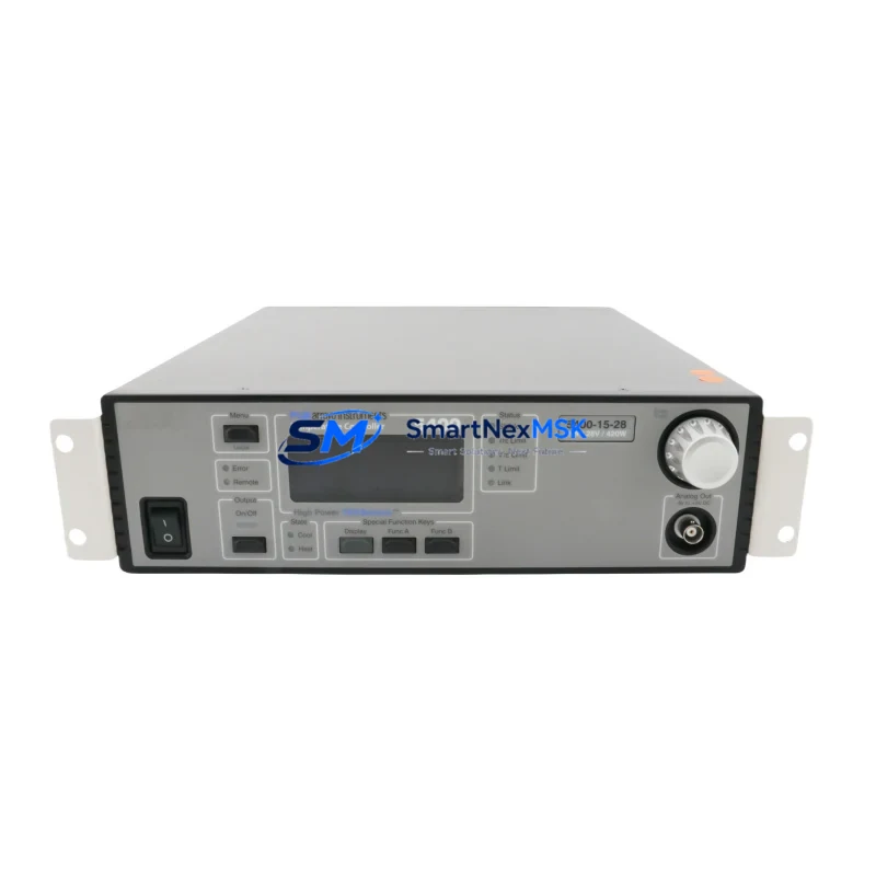
Power supply capacity is a key pre-check. The Centura I/O chassis is typically fed by a dedicated AMAT 0190-series DC power supply module; verify that the supply rail voltages (+5 V, ±15 V) are within specification before powering the new board. Loose or corroded terminal connections on the analog wiring harness are a common source of signal noise after a board swap — inspect and re-torque all field wiring terminals on the associated AMAT 0100-series terminal block assembly before commissioning.
For tools integrated into a fab-wide SECS/GEM communication framework, the analog I/O data reported by the 0100-20100 feeds into the equipment data acquisition (EDA) layer via the Centura host controller. After replacement, validate that all analog variable IDs (VIDs) are reporting correctly in the SECS-II data stream. If the tool uses an AMAT 0190-76038 VME communication card or similar backplane communication module, confirm that the I/O map has not shifted due to slot reassignment.
Facilities upgrading from older Centura configurations to newer process modules may also need to address compatibility with the AMAT 0100-09033 Digital I/O PCB, which often operates in adjacent slots and shares the same backplane bus. Coordinating the replacement of both analog and digital I/O boards during a single planned maintenance window reduces total exposure time and simplifies post-maintenance qualification. Similarly, if the tool’s AMAT 0190-40018 AC power distribution board is showing signs of age, replacing it concurrently is a best practice to avoid a secondary unplanned outage.
HMI screen validation is another critical step. Centura tools running Brooks Automation or legacy Applied Materials HMI software display analog process variables mapped directly to the I/O board channels. After installing the 0100-20100 replacement, cycle through all HMI process screens to confirm that pressure, temperature, flow, and RF power readings are within expected ranges and match the values shown on the tool’s independent gauges and meters. Any offset greater than the process specification tolerance should be corrected by adjusting the analog calibration constants in the recipe editor before resuming production wafers.
For facilities managing a mixed fleet that includes both Centura and Producer platforms, note that the AMAT 0100-20101 and AMAT 0100-20099 variants serve adjacent I/O functions on related platforms and may be required as part of a broader I/O subsystem refresh. Stocking these alongside the 0100-20100 ensures that a single maintenance event does not cascade into a multi-board shortage. The AMAT 0240-series robot controller boards and AMAT 0100-76050 process I/O interface cards are also commonly refreshed during Centura mid-life upgrades and should be evaluated as part of the same capital planning cycle.
All units supplied by SMARTNEXMSK are functionally tested prior to shipment. Each 0100-20100 board undergoes bench-level analog channel verification, backplane connector inspection, and component-level visual inspection. Units are shipped in ESD-safe packaging with a test report and a 12-month warranty certificate.
Downtime Control During System Migration
Minimizing chamber downtime during an analog I/O board replacement requires preparation before the tool is taken offline. The recommended approach is to pre-stage the replacement 0100-20100 board in the maintenance area, confirm its test report, and have all required tools, ESD wrist straps, and documentation ready before opening the equipment enclosure.
Before powering down, capture a full screenshot or printout of the current HMI process variable display and the Centura diagnostic I/O status screen. This baseline record allows rapid comparison after the board swap to identify any channel that is not recovering correctly. Save the current process recipe set to a backup location on the host controller to protect against accidental parameter loss during the maintenance event.
During the swap, label all analog wiring harness connectors before disconnecting them from the board. The Centura I/O chassis uses keyed connectors on most signal harnesses, but field-wired analog inputs are often terminated on removable screw-terminal blocks — photograph the terminal assignments before removal. Reinstall the terminal blocks on the new board in the same order and verify continuity on critical signal pairs before closing the enclosure.
After power-on, allow the Centura controller a full boot cycle before attempting to run a process recipe. Monitor the diagnostic screen for any I/O fault flags. If the system reports an analog channel out-of-range alarm, check the field wiring first before assuming a board fault — loose terminals account for the majority of post-swap analog errors. Once all channels are confirmed healthy, run a qualification wafer or process simulation before returning the tool to production. Total planned downtime for a prepared team is typically two to four hours, including post-swap qualification.
Retrofit Support FAQ
Q: Is the AMAT 0100-20100 a direct drop-in replacement for the original Applied Materials board?
A: Yes. The 0100-20100 supplied by SMARTNEXMSK is a functionally equivalent replacement for the original Applied Materials assembly. It uses the same backplane connector pinout and analog channel configuration, requiring no rack modification or firmware change for standard Centura installations.
Q: What pre-installation checks are required before swapping the board?
A: Verify DC supply rail voltages at the I/O chassis power input, confirm the slot address in the hardware configuration file, inspect all analog field wiring terminals for corrosion or looseness, and back up the current process recipe set. These steps take approximately 30 minutes and significantly reduce the risk of post-swap issues.
Q: How is the board tested before shipment?
A: Every 0100-20100 unit undergoes bench-level functional testing including analog channel signal verification, backplane connector inspection, and visual component inspection. A test report is included with each shipment. All units are covered by a 12-month warranty from the date of delivery.
Q: What should I do if an analog channel reads incorrectly after installation?
A: First, check the field wiring terminal connections for the affected channel — loose terminals are the most common cause of post-swap analog errors. If wiring is confirmed correct, compare the channel calibration constants in the process recipe against the baseline values captured before the swap. If the offset persists, contact SMARTNEXMSK technical support with the test report serial number for warranty assessment.
© 2026 SMARTNEXMSK. All rights reserved.
Original Source: https://smartnexmsk.com
Contact: sales@smartnexmsk.com | +86 18259474341