ASM LVC414 Retrofit-Ready Vaporizer Controller for LVC Series Control Systems
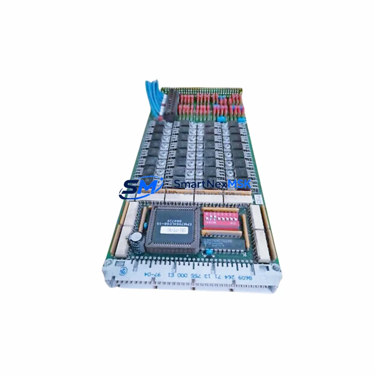
The ASM LVC414 is a retrofit-ready Vaporizer Controller Module engineered for seamless integration into existing LVC Series automation architectures. As semiconductor and industrial process facilities face increasing pressure to modernize aging control infrastructure, the LVC414 provides a validated, drop-in upgrade path that preserves original wiring layouts, backplane interfaces, and process logic — minimizing engineering rework and unplanned downtime during system migration.
Whether you are replacing a failed unit on an active production line, upgrading a legacy vaporizer control cabinet, or executing a planned system modernization, the LVC414 delivers the compatibility, reliability, and supply assurance that industrial procurement teams require. Each unit ships with a 12-month warranty, pre-shipment functional testing, and full traceability documentation.
Upgrade Compatibility Table
| Parameter | Details |
|---|---|
| SKU / Part Number | LVC414 |
| Brand | ASM (Advanced Semiconductor Materials) |
| Series | LVC Series Vaporizer Controller |
| Module Function | Vaporizer process control, temperature and flow regulation |
| Backplane Interface | Compatible with LVC Series rack and backplane connectors |
| Wiring Compatibility | Drop-in terminal-compatible with original LVC Series wiring harness |
| Communication Protocol | Compatible with existing LVC Series communication links (verify host controller interface prior to installation) |
| Power Supply Requirement | Verify rack power capacity before installation; confirm PSU output matches LVC414 rated draw |
| Replacement Recommendation | Direct replacement for discontinued LVC Series vaporizer controller variants |
| Commissioning Notes | Verify module address assignment, I/O mapping, and HMI tag references after installation |
| Warranty | 12 months from date of shipment |
| Pre-shipment Testing | Full functional test performed on every unit |
| Origin | Germany (OEM) |
| Shipping | Global express shipping available; Xiamen warehouse stock |
Retrofit Planning for Existing Automation Systems
Successful integration of the LVC414 into a legacy control system requires a structured pre-installation review. Engineers should begin by auditing the existing rack assembly to confirm available slot positions and backplane bus compatibility. In many LVC Series installations, the vaporizer controller shares a chassis with power distribution modules, analog I/O expansion cards, and dedicated communication interface modules — all of which must remain operational during the swap.
Before removing the original unit, document the current terminal wiring using the as-built drawings or perform a field trace if documentation is unavailable. The LVC414 maintains terminal-compatible pinouts with the standard LVC Series wiring harness, but engineers should verify that any field-modified wiring or non-standard cable assemblies are re-terminated correctly. Pay particular attention to shielded signal cables connected to temperature sensors and flow transducers, as improper grounding can introduce noise into the control loop.
The rack power supply — typically an LVC Series 24 VDC or 48 VDC PSU module — should be load-tested prior to installation to confirm it can support the LVC414 alongside co-installed modules such as digital input/output expansion cards and communication gateway modules. If the existing power supply is operating near capacity, a parallel power supply or replacement PSU should be staged before the maintenance window begins.
Module address configuration is a critical commissioning step. In LVC Series systems, the vaporizer controller module address is typically set via DIP switch or rotary selector on the module faceplate. Confirm the address assignment matches the original module’s configuration to avoid conflicts with other rack-resident modules, including analog signal conditioners, serial communication modules, and remote I/O adapters. Incorrect addressing will prevent the host controller or PLC from recognizing the LVC414 and may trigger system fault alarms.
HMI screen tag references should be reviewed before the system is returned to service. In facilities running SCADA or DCS platforms connected to the LVC Series rack, the vaporizer controller’s process variables — setpoint, actual temperature, flow rate, and alarm status — are typically mapped to named tags in the HMI project. Confirm that tag names and data types remain consistent with the LVC414’s register map to avoid display errors or control loop interruptions after restart.
For facilities migrating from older LVC Series variants to the LVC414 as part of a broader control system upgrade, the retrofit may also involve updating the programming cable connection to the host PLC or DCS controller, re-importing updated function block libraries, and re-validating interlock logic that references the vaporizer controller’s status outputs. Coordination with the process safety team is recommended where the vaporizer is integrated into emergency shutdown or safety instrumented system (SIS) logic.
Downtime Control During System Migration
Minimizing production downtime during an LVC414 retrofit requires careful pre-staging and a disciplined changeover sequence. The recommended approach is to complete all preparatory work — wiring documentation, address verification, HMI tag review, and spare parts staging — during normal production hours, reserving the physical module swap for a scheduled maintenance window.
Where process conditions permit, a cold-swap procedure is preferred: de-energize the rack, remove the original module, install the LVC414, verify terminal connections, restore power, and confirm module recognition by the host controller before resuming process control. In systems where continuous vaporizer operation is critical, coordinate with operations to identify the shortest viable maintenance window and prepare a rollback plan using the original module as a standby spare.
Original PLC or DCS program logic should be backed up to an offline storage device before any hardware changes are made. This protects against accidental program loss during power cycling and provides a reference baseline if post-installation tuning of control loop parameters is required. After the LVC414 is installed and recognized, perform a step-response test on the vaporizer control loop to confirm that PID parameters remain valid and that process response matches pre-retrofit behavior.
Field commissioning should include a full I/O checkout — verifying that each analog input from temperature sensors and flow meters reads correctly, that digital outputs to control valves and heater contactors respond as expected, and that all alarm and interlock signals are active and correctly routed. Document the commissioning results and retain them as part of the equipment maintenance record.
Retrofit Support FAQ
Q1: Is the LVC414 a direct drop-in replacement for my existing LVC Series vaporizer controller?
The LVC414 is designed as a retrofit-compatible replacement for LVC Series vaporizer controller variants. Terminal wiring and backplane interface are compatible with standard LVC Series rack configurations. However, engineers should verify module address settings, firmware revision compatibility with the host controller, and any site-specific wiring modifications before installation. Contact our technical team with your original part number for a confirmed replacement assessment.
Q2: What commissioning steps are required after installing the LVC414?
After physical installation, confirm module address assignment matches the original configuration, verify all terminal connections against as-built wiring drawings, restore system power and confirm host controller recognition, perform a full I/O checkout, validate HMI tag references, and execute a control loop step-response test. Document all commissioning results for maintenance records.
Q3: Can the LVC414 be used in systems with mixed communication protocols or legacy serial interfaces?
The LVC414 supports the communication interface standard for the LVC Series platform. For systems with mixed protocol environments — such as installations combining Modbus RTU, PROFIBUS DP, or proprietary serial links — verify that the host controller’s communication configuration matches the LVC414’s interface specification. If protocol conversion is required, a dedicated communication gateway module should be included in the retrofit bill of materials.
Q4: What does the 12-month warranty cover, and how is pre-shipment testing performed?
Every LVC414 unit undergoes full functional testing prior to shipment, including power-on verification, communication interface check, and I/O signal validation. The 12-month warranty covers manufacturing defects and functional failures under normal operating conditions from the date of shipment. Warranty claims are supported by our technical team with RMA processing and replacement unit dispatch. Units damaged by incorrect installation, overvoltage, or environmental factors outside the rated specification are not covered under the standard warranty.
© 2026 SMARTNEXMSK. All rights reserved.
Original Source: https://smartnexmsk.com
Contact: sales@smartnexmsk.com | +86 18259474341