ASM 02-007356D01 Maintenance-Ready Spare ET 200S Automation
The ASM 02-007356D01 is an original interface module designed for Siemens ET 200S distributed I/O systems, widely deployed in manufacturing lines, process automation cells, and machine control cabinets across automotive, chemical, and discrete manufacturing industries. As a maintenance-ready spare part, it is engineered to deliver direct drop-in replacement capability for aging or failed units in 6ES7 151-series IM configurations, minimizing unplanned downtime and restoring system communication integrity without requiring software reconfiguration or hardware adaptation.
For maintenance engineers managing aging PROFIBUS or PROFINET-based control architectures, the 02-007356D01 represents a critical line-replaceable unit (LRU). Its role in the ET 200S backplane is to bridge field-level I/O signals to the PLC controller — typically a Siemens S7-300 or S7-400 CPU — making it a single point of failure that demands immediate spare availability. Procurement engineers sourcing this module should treat it as a Tier-1 critical spare, maintaining at least one unit on-shelf per active ET 200S station in the facility.
Spare Maintenance Table
| Parameter | Specification |
|---|---|
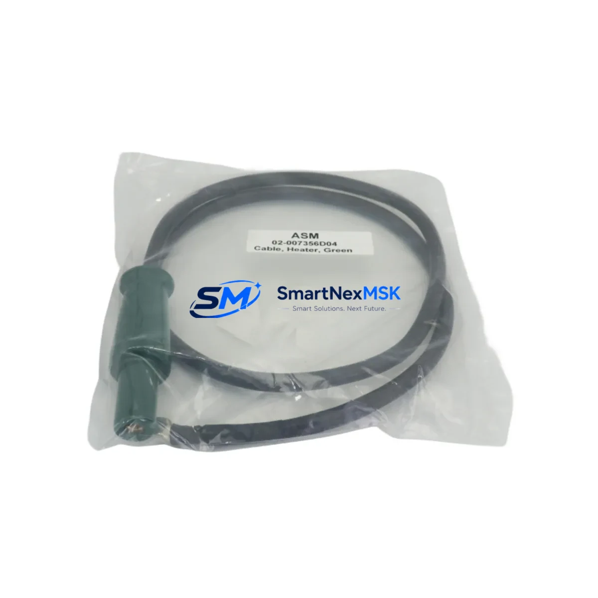
| Part Number / SKU | 02-007356D01 |
| Brand | ASM |
| Compatible Series | Siemens ET 200S Distributed I/O |
| Compatible IM Reference | 6ES7 151-3BA23-0AB0 |
| Module Type | Interface Module (IM) / Interface Cable |
| Communication Protocol | PROFIBUS DP / PROFINET (ET 200S platform) |
| Installation Method | DIN Rail, ET 200S backplane slot |
| Operating Temperature | 0 °C to +60 °C (standard industrial range) |
| Origin | Germany (DE) |
| Product Condition | Original, New / Tested Before Dispatch |
| Application Environment | Industrial control cabinets, distributed I/O stations, machine automation panels |
| Maintenance Role | Direct replacement for failed or degraded IM units in ET 200S stations |
| Warranty | 12 Months — Covers manufacturing defects and functional failure under normal operating conditions |
| Shipping | Tested before dispatch; ESD-safe packaging; express international available |
Maintenance Planning for Continuous Operation
When replacing the ASM 02-007356D01 interface module in an ET 200S station, a disciplined maintenance engineer will not stop at the IM itself. The surrounding electrical environment must be inspected to prevent repeat failures and ensure the restored station operates reliably through the next planned maintenance window.
Begin with the 24 VDC power supply module feeding the ET 200S rack — a degraded or undersized power supply is a common root cause of IM communication faults. Verify output voltage stability under load before re-energizing the station. Next, inspect the PROFIBUS DP connector or PROFINET patch cable at the IM port; connector corrosion, bent pins, or a damaged RJ45 are frequently overlooked failure contributors. If the station uses a 6ES7 193-4CA30-0AA0 terminal module beneath the IM, check for cracked housing or oxidized contacts that may cause intermittent signal loss.
For stations with mixed I/O, inspect the digital input modules (e.g., 6ES7 131-4BF00-0AA0) and digital output modules (e.g., 6ES7 132-4BF00-0AA0) seated on the same backplane. A failed IM can mask downstream I/O faults; once communication is restored, latent I/O errors may surface. Similarly, review any analog input or output modules in the station for drift or calibration deviation caused by power interruption during the original fault event.
If the ET 200S station interfaces with relay-controlled outputs, inspect the relay output modules and associated 24 VDC relay coils for contact wear — high-cycle relay positions adjacent to the IM are often due for replacement during the same maintenance event. For stations with signal isolators or surge protection modules on field wiring terminals, verify isolation resistance has not degraded. Finally, confirm that the S7-300 or S7-400 CPU rack upstream shows no residual hardware fault LEDs after the IM replacement, and that the STEP 7 or TIA Portal hardware configuration matches the physical slot assignment of the replacement module.
Procurement teams should consider stocking the 02-007356D01 alongside complementary spares: a spare ET 200S power module (PM-E), one set of PROFIBUS termination resistors, and a spare bus connector to cover the full scope of a rapid station recovery without waiting on additional parts delivery.
Site Replacement Workflow
Step 1 — Isolation: Place the affected ET 200S station in safe state via the PLC program (force outputs to safe position, acknowledge alarms). De-energize the station power supply and lock out / tag out (LOTO) per site procedure.
Step 2 — Documentation: Photograph the existing wiring, bus connector position, and module slot layout before removal. Note the PROFIBUS address or PROFINET device name configured on the outgoing IM — this must be preserved on the replacement unit.
Step 3 — Removal: Disconnect the PROFIBUS DP connector or PROFINET cable. Release the IM from the terminal module by pressing the release lever and sliding the module upward. Remove the terminal module if it also requires replacement.
Step 4 — Installation of ASM 02-007356D01: Seat the replacement module onto the terminal module, ensuring the backplane bus connector engages fully. Reconnect the field bus cable. Verify the PROFIBUS address switch or PROFINET name assignment matches the original configuration.
Step 5 — Commissioning: Re-energize the power supply. Observe the IM diagnostic LEDs — BF (Bus Fault) and SF (System Fault) LEDs should extinguish within the normal startup cycle. From the PLC engineering station, confirm the ET 200S station appears online in the hardware configuration and all I/O modules report no faults.
Step 6 — Functional Test: Cycle through I/O points associated with the station to confirm signal integrity. Document the replacement in the site maintenance log with date, technician ID, and new module serial number.
This workflow is designed to reduce mean time to repair (MTTR) to under 60 minutes for a trained technician with the spare on hand, compared to 4–24 hours waiting for emergency procurement.
Spare Parts Support FAQ
Q1: Is the ASM 02-007356D01 a direct replacement for the Siemens 6ES7 151-3BA23-0AB0 interface module?
The 02-007356D01 is an ASM-manufactured interface module compatible with the Siemens ET 200S platform and the 6ES7 151-3BA23-0AB0 reference. Before installation, verify the bus protocol (PROFIBUS DP vs. PROFINET), firmware revision requirements, and terminal module compatibility with your specific ET 200S station configuration. All units are tested before dispatch to confirm functional operation.
Q2: What is the recommended inventory strategy for this module?
For facilities operating 3 or more ET 200S stations, we recommend maintaining a minimum of 1–2 units of the 02-007356D01 as on-shelf critical spares. Given the module’s role as the primary communication gateway for the entire I/O station, a stockout during an unplanned failure can result in extended production downtime. Long-term supply continuity is supported — contact our team for blanket order arrangements and volume pricing.
Q3: How is the module tested before shipment?
Each ASM 02-007356D01 unit undergoes functional verification prior to dispatch, including communication interface continuity checks and visual inspection for physical damage. Units are shipped in ESD-safe packaging with individual labeling. A 12-month warranty covers manufacturing defects and functional failure under normal operating conditions from the date of delivery.
Q4: Can this module be used in a system running TIA Portal (STEP 7 V5.x and TIA Portal V15+)?
The ET 200S platform is supported under both STEP 7 Classic (V5.x) and TIA Portal environments. The hardware configuration in your engineering software must reflect the correct IM type and slot assignment. If you are migrating from an older ET 200S configuration to a newer TIA Portal project, confirm the GSD/GSDML file version matches the replacement module’s firmware. Our technical support team can assist with compatibility verification prior to order.
© 2026 SMARTNEXMSK. All rights reserved.
Original Source: https://smartnexmsk.com
Contact: sales@smartnexmsk.com | +86 18259474341