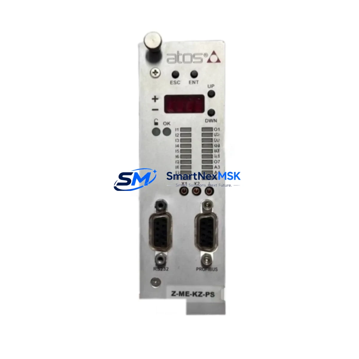
Atos Z-ME-KZ-PS Retrofit-Ready Axis Controller for Z-ME Series Control Systems
The Atos Z-ME-KZ-PS is a high-performance electrohydraulic axis position controller card engineered for seamless integration into existing Z-ME Series hydraulic control systems. Whether you are replacing a discontinued module, upgrading an aging control cabinet, or migrating a legacy proportional valve driver to a modern closed-loop architecture, the Z-ME-KZ-PS delivers the electrical compatibility, signal fidelity, and mechanical form factor required for a low-risk, minimum-downtime retrofit.
Designed for industrial environments where precision motion control is critical — including press lines, injection molding machines, die-casting equipment, and heavy-duty test rigs — this card supports ±10 V command input, integrated ramp generation, and enable/disable logic compatible with standard PLC digital output modules. Its onboard diagnostic LED indicators and fault relay output simplify commissioning and reduce troubleshooting time during system changeover.
Upgrade Compatibility Table
| Parameter | Z-ME-KZ-PS Specification | Retrofit Notes |
|---|---|---|
| Command Input | ±10 V DC analog / enable digital input | Compatible with standard PLC AO modules; verify signal ground reference |
| Supply Voltage | 24 V DC ±10% | Confirm existing 24 V rail capacity; add dedicated PSU if shared rail is loaded |
| Output Stage | Proportional solenoid driver, current-controlled | Verify coil resistance of existing proportional valve; re-tune current gain if replacing older Z-ME variant |
| Connector / Terminal | Screw terminal block, DIN rail mountable | Re-use existing cabinet wiring; confirm terminal pitch matches legacy harness |
| Communication | Analog signal interface (no fieldbus) | For fieldbus migration (PROFIBUS, EtherNet/IP), pair with a dedicated Atos digital axis card or gateway module |
| Mounting | DIN rail, standard 35 mm | Direct replacement in existing control cabinet; no panel modification required |
| Replacement Compatibility | Z-ME Series electrohydraulic cards | Confirm full SKU suffix (KZ-PS) matches valve coil type and feedback configuration |
| Commissioning Tool | Atos E-SW-CARD programming software | Required for ramp, dither, and gain parameter upload; retain original parameter file |
| Warranty | 12 Months | Covers manufacturing defects; includes pre-shipment functional test report |
Retrofit Planning for Existing Automation Systems
A successful retrofit with the Z-ME-KZ-PS begins well before the card arrives on site. Start by auditing the existing control cabinet: document the 24 V DC power supply capacity, confirm that the existing Atos Z-ME Series card slot dimensions and terminal assignments match the KZ-PS variant, and photograph the original wiring before disconnection. In many legacy installations, the proportional valve driver shares a 24 V rail with other devices — including solenoid valve coils, relay modules, and HMI panels — so verifying available current headroom is essential.
On the PLC side, the Z-ME-KZ-PS interfaces directly with standard analog output (AO) modules. If your control platform uses a Siemens S7-300 or S7-400 series CPU with an SM 332 analog output module, the ±10 V signal range is natively compatible. Similarly, Allen-Bradley ControlLogix or CompactLogix systems with 1756-OF8 or 1769-OF4 analog output cards will drive the Z-ME-KZ-PS without signal conditioning. For older systems using a Mitsubishi Q Series PLC with QD75 positioning module, verify that the analog output scaling matches the card’s input range before enabling the axis.
When the control system includes a Bosch Rexroth VT-HACD or similar legacy hydraulic axis controller that is being decommissioned, the Z-ME-KZ-PS can serve as a direct functional replacement in the same cabinet slot, provided the proportional valve coil impedance is within the card’s driver range. In systems where the original card communicated via a proprietary serial link to an HMI, plan to remap the axis status signals — enable feedback, fault relay, and position reached — to the PLC’s digital input (DI) module so that the HMI screen logic remains intact without reprogramming the visualization layer.
For I/O expansion during the retrofit, consider whether additional Atos E-RI-AES position transducer interface modules or external LVDT signal conditioners are needed to close the position loop. If the original system used a potentiometer-based position feedback and the new installation requires higher resolution, this is the appropriate stage to upgrade the feedback sensor and reconfigure the card’s feedback input scaling accordingly.
Cable routing and shielding deserve particular attention. The analog command signal and feedback wiring should be routed in separate cable ducts from power wiring to prevent interference. Use shielded twisted-pair cable, connect the shield at the card end only, and verify that the cabinet earth bonding meets IEC 61439 requirements. These steps are especially important in retrofit scenarios where the existing cable infrastructure was installed to older standards.
Downtime Control During System Migration
Minimizing production downtime during a Z-ME-KZ-PS retrofit requires a structured changeover plan. Begin by creating a full backup of the PLC program — including all data blocks, function blocks, and hardware configuration — using the appropriate programming environment (STEP 7, TIA Portal, Studio 5000, or GX Works depending on your control platform). Export the original Atos card parameters using the E-SW-CARD software and store the file with the project documentation. This ensures that if the new card requires parameter adjustment during commissioning, the baseline configuration is always recoverable.
Where production schedules allow, perform a bench test of the Z-ME-KZ-PS before installation. Connect the card to a 24 V DC bench supply, apply a simulated ±10 V command signal from a signal generator or a spare PLC AO channel, and verify the output current response against the valve coil specification. This pre-shipment verification — combined with the 12-month warranty coverage — significantly reduces the risk of discovering a configuration mismatch after the machine has been taken offline.
During the physical swap, label all terminals before disconnection, replace one card at a time in multi-axis systems, and restore power incrementally. After power-up, use the card’s onboard LED diagnostics to confirm the enable signal is active and no fault condition is present before commanding axis movement. Perform a slow-speed functional test at 10–20% of full command range before returning the machine to automatic cycle. This staged approach protects the original program logic, preserves HMI screen continuity, and keeps the control loop stable throughout the transition.
In systems where continuous operation is required, consider a parallel run strategy: install the Z-ME-KZ-PS in a spare slot or temporary test cabinet, validate its response against the live axis using a Y-split on the command signal, and only cut over to the new card once the response curves match. This approach is particularly effective in press and injection molding applications where axis tuning directly affects part quality.
Retrofit Support FAQ
Q1: Is the Z-ME-KZ-PS a direct drop-in replacement for all Z-ME Series cards?
The Z-ME-KZ-PS is compatible with the Z-ME Series form factor and terminal layout, but the KZ-PS suffix denotes a specific coil driver configuration and feedback input type. Always verify the full SKU suffix of the card being replaced. If the original card carried a different suffix (e.g., Z-ME-KZ or Z-ME-RS), confirm that the proportional valve coil impedance and feedback sensor type are compatible before installation. Our pre-shipment test report documents the card’s output characteristics to support this verification.
Q2: What commissioning steps are required after installation?
After physical installation and wiring, connect the card to the Atos E-SW-CARD programming software via the card’s serial interface. Upload the saved parameter file from the original card (ramp times, dither frequency, current gain, and enable logic polarity). Perform a slow-speed axis movement test to verify the command-to-output relationship, then incrementally increase the command range to full stroke. Check the fault relay output and LED status at each stage. Full commissioning typically requires 2–4 hours for a single-axis replacement.
Q3: Can the Z-ME-KZ-PS be used in a system that is migrating from analog to fieldbus control?
The Z-ME-KZ-PS operates on an analog ±10 V command interface and does not natively support PROFIBUS, EtherNet/IP, or CANopen. For fieldbus migration, the card can be retained as the valve driver stage while a fieldbus-to-analog gateway or a digital Atos axis card (such as the Z-ME-D Series) is introduced upstream to handle the protocol conversion. This hybrid approach allows the hydraulic valve and mechanical system to remain unchanged while the control architecture is modernized incrementally.
Q4: What does the 12-month warranty cover, and what documentation is provided?
The 12-month warranty covers manufacturing defects in materials and workmanship from the date of shipment. Each unit is supplied with a pre-shipment functional test report confirming output current linearity, enable logic response, and fault relay operation. In the event of a warranty claim, the card is repaired or replaced at no charge. Warranty service is coordinated through sales@smartnexmsk.com. Proof of purchase and the test report serial number are required to initiate a claim.
© 2026 SMARTNEXMSK. All rights reserved.
Original Source: https://smartnexmsk.com
Contact: sales@smartnexmsk.com | +86 18259474341