Bosch Rexroth RKP-PQ Retrofit-Ready P/Q Control for RKP Series: Compatible Modernization & Smooth System Upgrade
The Bosch Rexroth RKP-PQ is a pressure/flow (P/Q) control module engineered for the RKP axial piston pump series — one of the most widely deployed variable-displacement hydraulic pump platforms in industrial automation, press control, injection molding, and mobile machinery. As legacy RKP-series installations age and original P/Q control assemblies reach end-of-life or become discontinued, the RKP-PQ serves as the authoritative retrofit-ready replacement, enabling engineers to restore full closed-loop pressure and flow regulation without redesigning the hydraulic circuit or replacing the pump body.
For facilities running aging Bosch Rexroth RKP 45, RKP 63, RKP 100, or RKP 140 frame-size pumps, sourcing a verified RKP-PQ control module is often the fastest path to restoring machine uptime. The module mounts directly to the pump’s control port, retaining the original SAE flange interface and pilot pressure supply line. Engineers familiar with the Bosch Rexroth A10VSO or A4VSO series will recognize the control philosophy — proportional solenoid-driven spool, integrated pressure-limiting valve, and a separate flow setpoint input — making cross-training and commissioning straightforward for experienced hydraulic technicians.
Before installation, retrofit planners must verify several critical parameters. First, confirm the pump’s rated displacement (cc/rev) and maximum operating pressure against the RKP-PQ’s control range to ensure the setpoint potentiometers or analog command signals (typically 0–10 V DC or 4–20 mA) are correctly scaled. Second, inspect the existing terminal block wiring: the solenoid coil connector (typically Deutsch DT or AMP Superseal format on RKP-series controls) must match the replacement module’s connector body, or an adapter harness must be prepared in advance. Third, verify the pilot pressure supply — the RKP-PQ requires a stable internal or external pilot pressure (typically 25–35 bar) drawn from the pump’s case drain or a dedicated pilot circuit; insufficient pilot pressure is the most common cause of control instability after retrofit.
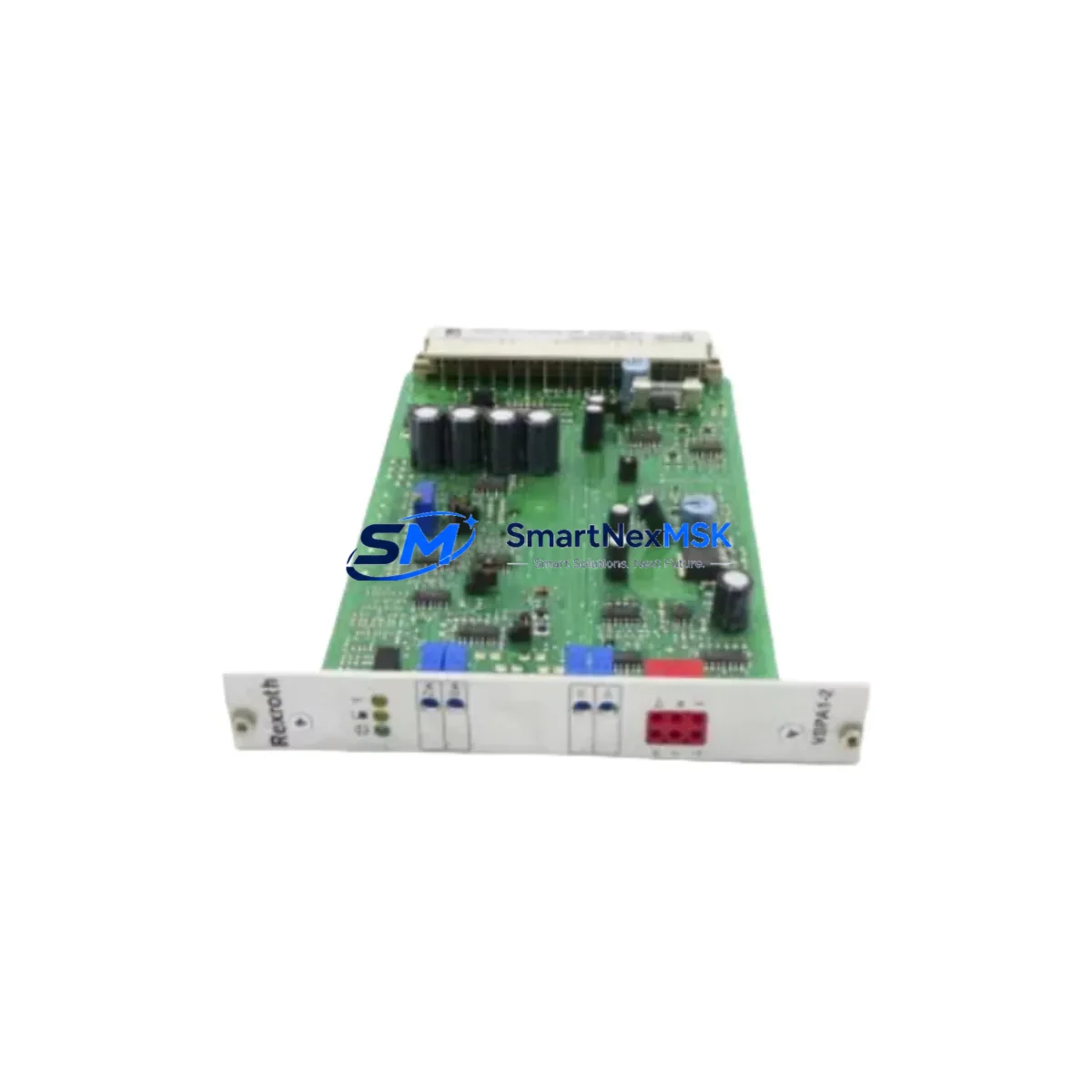
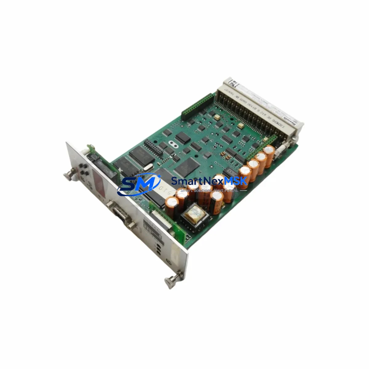
In control cabinet upgrades, the RKP-PQ is frequently paired with a Bosch Rexroth VT-HACD proportional amplifier card or a VT-MSPA1 analog servo amplifier mounted in a 19-inch rack or DIN-rail enclosure. These amplifier cards provide the closed-loop PID regulation, ramp function generation, and enable/disable logic that the RKP-PQ control module requires for stable operation. If the existing amplifier card is also discontinued or damaged, it should be replaced simultaneously to avoid mismatched control dynamics. The Bosch Rexroth VT-HACD-1-1X is a common direct replacement for older VT-HACD variants and is compatible with the RKP-PQ’s solenoid current requirements.
For systems integrating the RKP pump into a broader Rexroth IndraControl or Sytronix variable-speed drive platform, the RKP-PQ control module may interface with a Rexroth IndraDrive Cs or IndraDrive M servo drive via analog command output. In these architectures, the drive’s analog output card — such as the Rexroth HCS02 analog I/O expansion — provides the 0–10 V setpoint signal to the RKP-PQ, while the drive itself manages motor speed for energy-efficient variable-flow operation. Verifying the analog output scaling and ground reference between the drive and the RKP-PQ control module is essential before enabling closed-loop operation.
Communication protocol migration is another consideration in modern retrofit projects. Older RKP installations may rely on hardwired analog setpoints from a legacy Siemens S5 or Allen-Bradley SLC 500 PLC analog output module. Migrating to a current-generation controller — such as a Siemens S7-1500 with a 6ES7 532 analog output module, or an Allen-Bradley ControlLogix 1756-OF8 — requires confirming that the new analog output module can source the correct current or voltage range expected by the RKP-PQ solenoid driver. A signal isolator or scaling module may be required if the legacy wiring uses a different reference ground.
Backplane and rack considerations apply when the RKP-PQ is part of a larger hydraulic power unit (HPU) control panel. In multi-pump HPU configurations, each pump’s P/Q control module typically receives its setpoint from a dedicated analog output channel on the PLC rack. Ensuring that the rack’s power supply — for example a Siemens 6EP1 SITOP PSU or Phoenix Contact QUINT-PS — can sustain the additional solenoid coil current draw after adding or replacing the RKP-PQ module is a pre-commissioning checklist item that is frequently overlooked.
HMI screen updates are required when the RKP-PQ replaces a control module with different engineering unit scaling. If the existing Siemens TP700 Comfort or Weintek MT8000 HMI panel displays pressure and flow setpoints in bar and L/min derived from the old module’s transfer function, the tag scaling in the HMI project must be recalculated and re-downloaded to reflect the RKP-PQ’s actual gain and offset. Failure to update HMI scaling is a common source of post-retrofit operator complaints about incorrect readings even when the hydraulic system is performing correctly.
All RKP-PQ modules supplied by SMARTNEXMSK are subject to pre-shipment functional testing: solenoid coil resistance measurement, pilot pressure response verification, and setpoint linearity check across the full command range. Each unit ships with a test report and is covered by a 12-month warranty against manufacturing defects and functional failure under normal operating conditions. Stock is maintained for immediate dispatch, with typical lead time of 3–7 business days for international destinations.
Upgrade Compatibility Table
| Parameter | Detail |
|---|---|
| SKU | RKP-PQ |
| Brand | Bosch Rexroth |
| Compatible Pump Series | RKP 45 / RKP 63 / RKP 100 / RKP 140 |
| Control Function | Pressure/Flow (P/Q) Combined Control |
| Mounting Interface | SAE flange, direct pump-mount |
| Command Signal | 0–10 V DC / 4–20 mA (configurable) |
| Pilot Pressure Requirement | 25–35 bar (internal or external pilot) |
| Solenoid Connector | Deutsch DT / AMP Superseal (verify before order) |
| Replacement Compatibility | Drop-in for discontinued OEM RKP-PQ assemblies |
| Amplifier Card Compatibility | Bosch Rexroth VT-HACD, VT-MSPA1 series |
| Communication | Analog hardwired (0–10 V / 4–20 mA); no fieldbus required |
| Commissioning Requirement | Pilot pressure check, solenoid wiring, HMI scaling update |
| Pre-shipment Testing | Coil resistance, pilot response, setpoint linearity |
| Warranty | 12 Months — manufacturing defects & functional failure |
| Origin | Germany (DE) |
| Lead Time | 3–7 business days international |
Retrofit Planning for Existing Automation Systems
A successful RKP-PQ retrofit begins with a structured pre-engineering review. The technician should collect the existing pump nameplate data (displacement, max pressure, speed range), the current wiring diagram for the P/Q control solenoids, and the PLC analog output module specification sheet. In most legacy installations, the analog output originates from a Siemens S7-300 SM 332 analog output module or an Allen-Bradley 1746-NO4I SLC 500 analog output, both of which are compatible with the RKP-PQ’s input range after confirming signal polarity and ground isolation.
The control cabinet layout should be reviewed to confirm available DIN-rail space for any replacement amplifier card. If the existing Bosch Rexroth VT-HACD amplifier is retained, its enable relay wiring and ramp time settings must be documented before removal of the old P/Q module, as these parameters directly affect how quickly the RKP-PQ responds to setpoint changes during machine startup. A Bosch Rexroth VT-VSPA2 proportional valve amplifier may also be present in the same cabinet if the HPU includes proportional directional valves — its settings are independent of the RKP-PQ but should be documented as part of the overall cabinet audit.
For I/O mapping, confirm that the PLC program’s analog output channel address correctly maps to the physical terminal on the new module. In Siemens TIA Portal, this means verifying the hardware configuration’s I/O address assignment for the SM 532 or ET 200SP analog output module. In Rockwell Studio 5000, confirm the 1756-OF8 module’s channel scaling matches the RKP-PQ’s expected input range. A Phoenix Contact MINI MCR signal conditioner is recommended as an intermediate scaling device when the PLC output range does not precisely match the RKP-PQ input specification.
Terminal block wiring should follow the RKP-PQ’s connection diagram precisely. Use ferrule-terminated 0.75 mm² or 1.0 mm² flexible cable for solenoid connections, and ensure the shield drain wire is grounded at one end only (typically at the cabinet earth bar) to prevent ground loops that can cause setpoint drift. Label all terminals with the new module’s reference designators before energizing the circuit.
Downtime Control During System Migration
Minimizing production downtime during an RKP-PQ retrofit requires a parallel preparation strategy. All wiring, amplifier card configuration, and HMI scaling updates should be completed and verified on the bench or in simulation before the machine is taken offline. The PLC program logic controlling the hydraulic enable sequence — typically a combination of pressure-OK feedback, pump run permissive, and E-stop chain — should be exported and backed up before any hardware changes are made.
During the physical swap, the pump does not need to be removed from the machine. The RKP-PQ control module unbolts from the pump’s control port with standard hex keys, and the replacement module installs in reverse order. The entire mechanical swap typically takes under 30 minutes for an experienced hydraulic technician. The majority of retrofit time is spent on electrical reconnection, pilot pressure verification, and initial setpoint calibration.
After installation, perform a slow-ramp commissioning sequence: start the pump at minimum displacement (minimum flow command), verify pilot pressure is within specification, then gradually increase the flow setpoint while monitoring system pressure on a calibrated gauge. Do not enable the pressure-limiting function until flow control is confirmed stable. This staged approach protects the original program logic and prevents pressure spikes that could damage downstream actuators or valves.
If the machine uses a Bosch Rexroth IndraControl L45 or similar integrated motion controller with embedded hydraulic axis control, the axis parameterization (Kv gain, velocity feedforward, pressure limit) should be re-verified after the RKP-PQ swap, as slight differences in control module gain between old and new units can shift the closed-loop response. A brief auto-tuning cycle or manual gain adjustment in the IndraWorks DS commissioning tool will restore optimal performance.
Retrofit Support FAQ
Q1: Is the RKP-PQ a direct drop-in replacement for the original Bosch Rexroth P/Q control on my RKP pump?
A: Yes, for RKP 45, 63, 100, and 140 frame sizes, the RKP-PQ mounts directly to the pump’s control port using the original SAE flange and fastener pattern. Solenoid connector compatibility should be confirmed against your existing wiring harness before ordering — contact us with your pump nameplate data for a pre-order compatibility check.
Q2: What commissioning steps are required after installing the RKP-PQ?
A: The key commissioning steps are: (1) verify pilot pressure is 25–35 bar at the control port, (2) confirm solenoid wiring polarity and connector seating, (3) apply minimum command signal and check for smooth displacement response, (4) update HMI tag scaling if the old module had different engineering unit conversion, and (5) perform a full-range setpoint sweep to verify linearity before returning the machine to production.
Q3: Can the RKP-PQ work with my existing Siemens S7-300 or Allen-Bradley SLC 500 analog output?
A: Yes, provided the analog output module is configured for 0–10 V DC or 4–20 mA output within the RKP-PQ’s input specification. A signal isolator or scaling module (e.g., Phoenix Contact MINI MCR) may be required if the output range or ground reference does not match. We recommend sharing your PLC analog output module datasheet for a pre-installation compatibility review.
Q4: What does the 12-month warranty cover, and how is it claimed?
A: The 12-month warranty covers manufacturing defects and functional failure under normal operating conditions, including solenoid coil failure, spool stiction, and pilot pressure response degradation. It does not cover damage from incorrect installation, contaminated hydraulic fluid, or operation outside the rated pressure and temperature range. To claim warranty service, contact sales@smartnexmsk.com with your order number and a description of the fault; we will arrange return, inspection, and replacement or repair within 10 business days of receipt.
© 2026 SMARTNEXMSK. All rights reserved.
Original Source: https://smartnexmsk.com
Contact: sales@smartnexmsk.com | +86 18259474341