Danaher Motion SPD36006-00 Spare for SPD36000 Automation
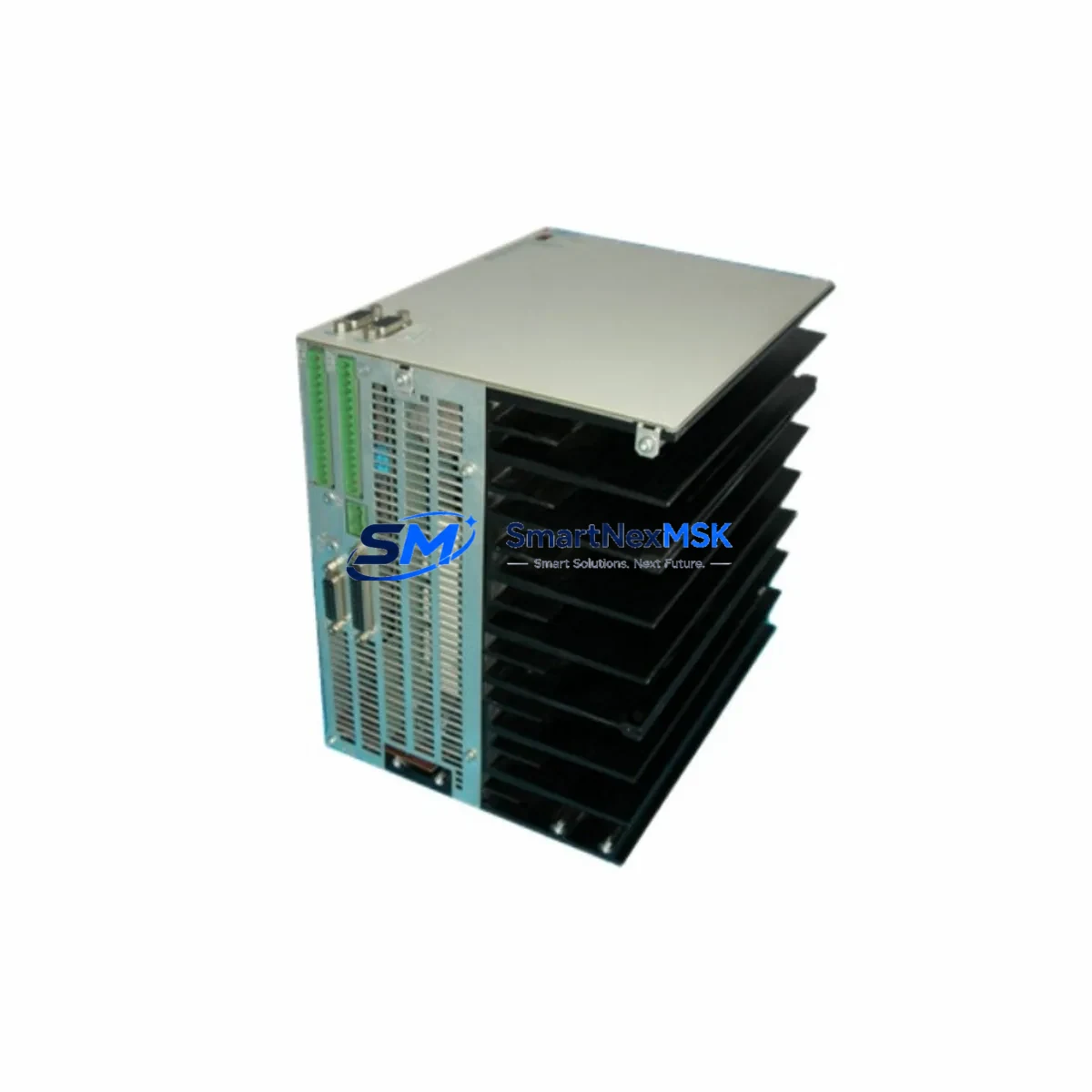
The Danaher Motion SPD36006-00 is an original servo drive control interface board engineered for the SPD36000 series servo drive platform. In industrial automation environments where servo axes control precision motion — from CNC machining centers and packaging lines to press-feed systems and robotic assembly cells — the interface board is the critical communication bridge between the drive’s power stage and the motion controller. A failed SPD36006-00 can halt an entire production line within seconds, making rapid spare parts availability a core element of any maintenance strategy.
Sourced as an original Danaher Motion component, the SPD36006-00 is fully tested prior to shipment and backed by a 12-month warranty. Each unit undergoes functional verification to confirm signal integrity, connector condition, and firmware compatibility before dispatch. Whether you are managing a planned overhaul, responding to an unscheduled fault, or building a strategic spare parts buffer, the SPD36006-00 is available for fast worldwide dispatch.
Spare Maintenance Table
| Parameter | Specification / Detail |
|---|---|
| Part Number | SPD36006-00 |
| Brand | Danaher Motion |
| Series | SPD36000 |
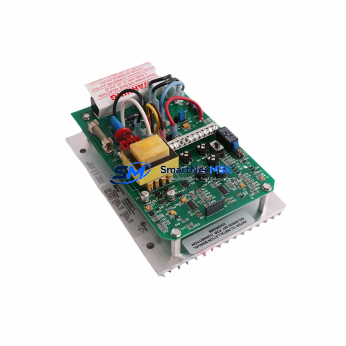
| Product Type | Servo Drive Control Interface Board |
| Component Role | Signal interface between motion controller and drive power stage |
| Compatibility | SPD36000 series servo drives; verify drive firmware revision before installation |
| Connector Type | Multi-pin ribbon and D-sub interface connectors (verify against drive documentation) |
| Installation Environment | Control cabinet, DIN-rail or panel-mount servo drive enclosure |
| Operating Temperature | 0 °C to +55 °C (standard industrial cabinet range) |
| Origin | USA (Danaher Motion OEM) |
| Condition | Original, tested before shipment |
| Warranty | 12 Months |
| Shipping | Worldwide express; DHL / FedEx / UPS available |
| Maintenance Recommendation | Replace as matched pair with drive power board during major overhaul; inspect connectors and ribbon cables at each planned maintenance interval |
Maintenance Planning for Continuous Operation
When a maintenance or procurement engineer identifies the SPD36006-00 as a fault source or a planned replacement item, the scope of inspection should extend beyond the interface board itself. The SPD36000 series drive operates within a broader electrical ecosystem, and a thorough site assessment significantly reduces the risk of repeat failures and secondary downtime.
Begin with the servo drive power supply module feeding the SPD36000 drive. Unstable DC bus voltage or ripple on the 24 VDC logic rail is a leading cause of premature interface board failure. Verify that the power supply output is within specification and that filter capacitors show no signs of bulging or leakage. At the same time, inspect the 24 VDC control power fuse and any associated fuse holders in the cabinet — a marginal fuse that passes continuity testing under low load may still fail under inrush conditions.
Check the encoder feedback cable and its associated connector at both the motor and drive ends. Damaged shielding or intermittent contacts on the encoder line can produce fault codes that mimic interface board failures. Similarly, inspect the I/O terminal block wiring connected to the drive’s digital inputs and outputs — loose terminations on enable signals, fault reset lines, or speed reference inputs are a common source of nuisance faults that stress the interface board’s signal conditioning circuitry.
If the SPD36000 drive communicates with a PLC or motion controller via a fieldbus communication module (such as a PROFIBUS-DP or DeviceNet adapter card), verify that the communication module is seated correctly and that the network termination resistors are in place. A communication timeout fault can trigger drive shutdown sequences that place repeated stress on the interface board’s logic circuits.
For cabinets housing multiple servo axes, inspect the shared DC bus capacitor bank and any braking resistor or dynamic braking module. Excessive regenerative energy that is not properly dissipated can cause DC bus overvoltage events that damage interface boards across multiple drives simultaneously. Also review the contactor and relay logic in the main power circuit — worn contactor contacts produce voltage spikes at power-on that can degrade sensitive interface board components over time.
Finally, if the system includes a Danaher Motion HMI operator panel or a third-party HMI connected to the drive’s serial port, verify the communication cable integrity and the HMI’s parameter backup. Restoring drive parameters from a verified backup after interface board replacement eliminates the risk of misconfiguration and accelerates recommissioning. Maintaining a signal isolator on any analog speed or torque reference input is also recommended to protect the new interface board from ground loop interference originating in the wider plant electrical system.
Site Replacement Workflow
Replacing the SPD36006-00 in the field follows a structured sequence designed to minimize downtime and ensure system compatibility:
1. Fault Confirmation: Before ordering, confirm the fault is isolated to the interface board. Use the drive’s diagnostic LED indicators and fault code log to rule out encoder, power supply, or motor winding faults. If the drive displays a persistent control board fault code that clears with a known-good interface board swap, the SPD36006-00 is confirmed as the failed component.
2. Drive Parameter Backup: Before removing the existing board, back up all drive parameters to the HMI, a laptop running the Danaher Motion commissioning software, or a parameter storage card if supported. This step is critical — parameter loss after board replacement is a common cause of extended recommissioning time.
3. Safe Isolation: Isolate the drive from mains power and allow the DC bus capacitors to discharge fully (minimum 5 minutes, verify with a calibrated voltmeter). Discharge the 24 VDC control supply as well before handling the interface board.
4. Board Removal and Inspection: Remove the SPD36006-00 carefully, noting connector positions and any jumper or DIP switch settings. Inspect the drive chassis for signs of overheating, contamination, or corrosion that may have contributed to the failure.
5. Replacement Installation: Install the new SPD36006-00, ensuring all connectors are fully seated and ribbon cables are correctly oriented. Replicate any jumper or switch settings from the removed board.
6. Parameter Restore and Commissioning: Restore drive parameters from backup. Power up in a controlled sequence, verify fault-free operation at low speed before returning the axis to full production duty.
This workflow is compatible with both direct like-for-like replacement of the SPD36006-00 and scenarios where the drive is being upgraded from an older SPD36000 variant. Compatibility with the specific drive firmware revision should always be confirmed with the part documentation prior to installation.
Spare Parts Support FAQ
Q: What is the warranty coverage for the SPD36006-00?
A: Every SPD36006-00 supplied by SMARTNEXMSK is covered by a 12-month warranty from the date of shipment. The warranty covers functional defects confirmed through our pre-shipment testing protocol. Units are tested for signal integrity, connector condition, and basic operational function before dispatch.
Q: How do I verify compatibility between the SPD36006-00 and my specific SPD36000 drive variant?
A: Provide your drive’s full model number and firmware revision to our technical team at sales@smartnexmsk.com. We will cross-reference against our compatibility database and confirm suitability before shipment. For legacy SPD36000 variants, we can also advise on any known hardware revision differences.
Q: Can you support long-term or blanket purchase orders for the SPD36006-00?
A: Yes. SMARTNEXMSK supports scheduled delivery agreements and strategic stock programs for maintenance teams managing multiple SPD36000 drives. Contact us to discuss volume pricing, lead time commitments, and consignment stock arrangements tailored to your planned maintenance calendar.
Q: What pre-shipment testing is performed on each SPD36006-00?
A: Each unit undergoes functional verification including connector integrity checks, signal path continuity, and visual inspection for component damage or contamination. Units that do not pass all test criteria are not shipped. A test report is available on request for critical applications.
© 2026 SMARTNEXMSK. All rights reserved.
Original Source: https://smartnexmsk.com
Contact: sales@smartnexmsk.com | +86 18259474341