Eaton L630E 0040-03154 Retrofit-Ready MCCB for Series C Control Systems
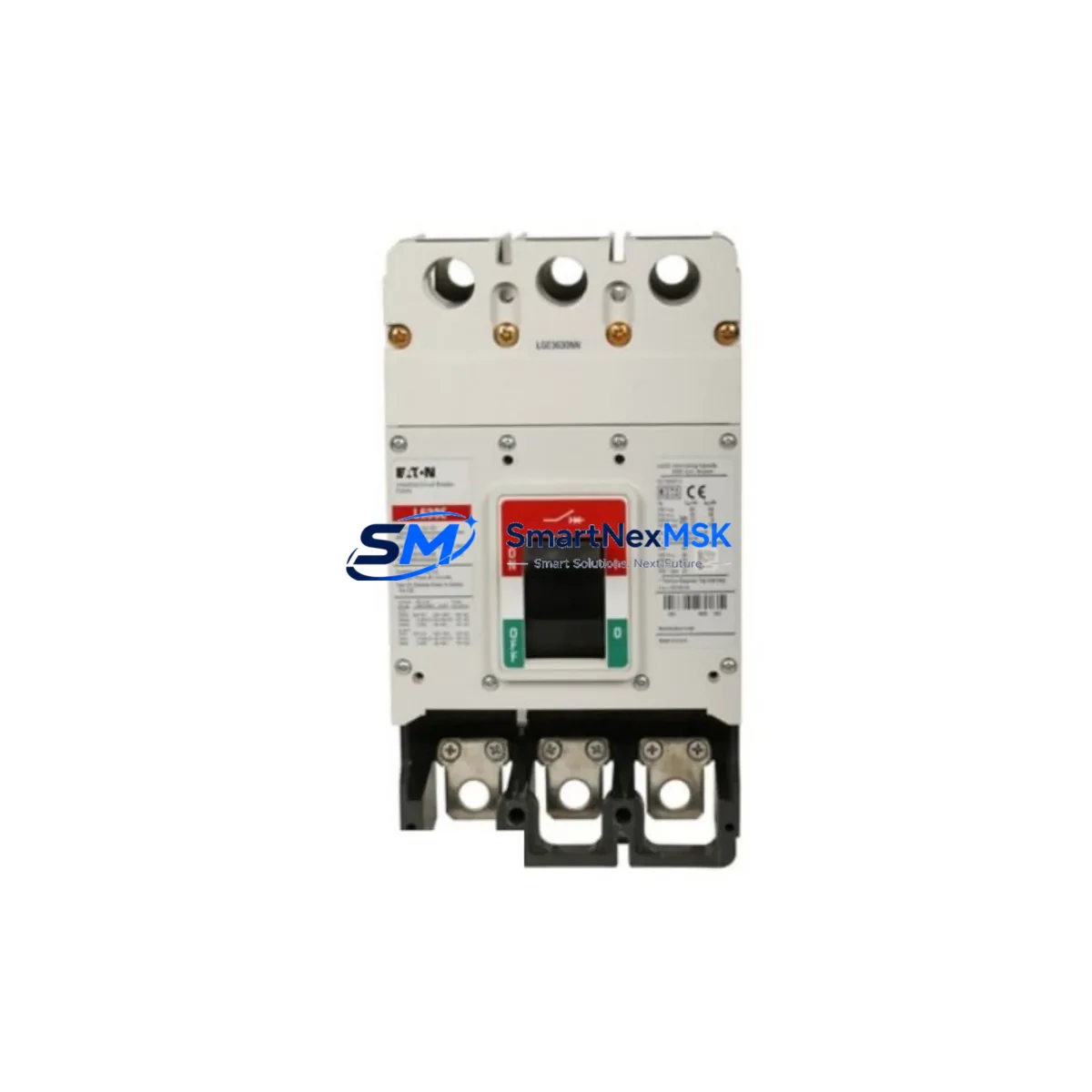
The Eaton L630E (SKU: L630E 0040-03154 / 8124063G001) is a 630A, 3-pole molded case circuit breaker engineered for seamless integration into legacy and modern Series C control systems. As industrial facilities face increasing pressure to modernize aging electrical infrastructure without full panel replacements, the L630E stands out as a proven retrofit solution — offering direct dimensional compatibility, equivalent interrupting ratings, and full compliance with IEC 60947-2 standards that legacy installations depend on.
Whether you are replacing an end-of-life breaker in a motor control center (MCC), upgrading a main incomer in a distribution panel, or restoring protection to a critical production line, the L630E delivers the electrical performance and mechanical fit required for a smooth, low-risk changeover. Its fixed-mount design aligns with standard DIN rail and busbar configurations found across Series C switchgear assemblies, eliminating the need for panel modification or custom adapters.
Upgrade Compatibility Table
| Parameter | Specification / Recommendation |
|---|---|
| Rated Current | 630A |
| Poles | 3P |
| Frame Series | Series C (direct replacement) |
| Part Numbers | L630E / 0040-03154 / 8124063G001 |
| Mounting Interface | Fixed mount; compatible with standard Series C busbar pitch |
| Terminal Type | Front-connected lug terminals; verify cable cross-section ≥ 240mm² |
| Communication Compatibility | Compatible with Eaton IQ series metering and PROFIBUS-DP gateway modules where applicable |
| Replacement Recommendation | Direct drop-in for L630E legacy units; verify trip unit calibration after installation |
| Commissioning Focus | Torque terminal connections per Eaton spec; test trip curve with secondary injection |
| Warranty | 12 months from date of shipment |
Retrofit Planning for Existing Automation Systems
Successful retrofit of the L630E into an existing Series C control system requires a structured pre-installation review. Begin by auditing the upstream transformer capacity and confirming that the 630A continuous rating does not exceed 80% of the feeder’s design load. In many legacy installations, the original Eaton NZM series or Moeller PKZM motor protection switches were installed alongside the main MCCB — these components must be re-evaluated for coordination selectivity when the main breaker is replaced.
Terminal wiring is a critical checkpoint. The L630E uses front-connected lug terminals rated for cables up to 300mm². If the existing installation uses rear-connected busbars from an older Eaton xEnergy or Moeller CI-K4 busbar system, a terminal adapter kit may be required. Confirm busbar pitch and phase spacing before ordering. In retrofit scenarios involving Eaton IZM series air circuit breakers in the same switchboard, ensure that the zone-selective interlocking (ZSI) wiring between the IZM and the L630E’s trip unit is re-terminated correctly to maintain upstream/downstream coordination.
For systems incorporating Eaton EU5E Ethernet gateways or SmartWire-DT (SWD) communication modules, the L630E can be integrated into the existing network topology without protocol migration — the SWD gateway continues to poll downstream motor starters and I/O modules independently of the main breaker. However, if the control system uses a Modbus RTU or PROFIBUS-DP backbone, verify that the energy metering module (such as the Eaton IQ 250 power meter) upstream of the L630E is reconfigured to reflect the new breaker’s CT ratio and rated current.
Panel builders and maintenance engineers should also account for the auxiliary contact block configuration. The L630E supports up to four auxiliary contacts (2NO + 2NC standard), which are typically wired into the PLC digital input module for remote status monitoring. If the legacy installation used an older Eaton DILM series contactor interlock scheme, confirm that the auxiliary contact wiring diagram is updated in the as-built documentation before energizing. The Eaton XC200 PLC or equivalent controller managing the MCC should have its I/O address map reviewed to ensure the new breaker’s status signals are correctly mapped.
Finally, if the retrofit involves replacing multiple breakers across a multi-tier distribution board, consider staging the replacement by feeder priority — starting with non-critical circuits to validate the installation procedure before moving to production-critical feeders. Keep the original Eaton L630E trip unit settings documented and replicate them on the replacement unit using the Eaton PowerXpert software or manual DIP switch configuration as applicable to your trip unit variant.
Downtime Control During System Migration
Minimizing production downtime during an MCCB replacement is achievable with disciplined pre-staging and a clear switching sequence. Before the maintenance window opens, pre-assemble the L630E with all required accessories — auxiliary contacts, shunt trip coil, and undervoltage release — and perform a bench-level functional test. Verify that the trip unit is set to match the original overcurrent and short-circuit thresholds documented in the panel’s protection coordination study.
During the outage, photograph all terminal connections before disconnection and label each cable with its circuit designation. Use a torque wrench to tighten lug connections to Eaton’s published values (typically 20–25 Nm for 630A terminals) to prevent thermal failures under load. After re-energization, perform a secondary injection test on the trip unit and confirm that the PLC digital inputs correctly reflect the breaker’s CLOSED and TRIPPED states. If the system uses an Eaton HMI (XV-152) or SCADA screen with breaker status graphics, update the display tag mapping to reflect any I/O address changes introduced during the retrofit. A structured commissioning checklist — covering power-on sequence, load ramp-up, and alarm acknowledgment — ensures that the control system returns to full operational status within the planned maintenance window, protecting both equipment and production continuity.
Retrofit Support FAQ
Q1: Is the Eaton L630E 0040-03154 a direct replacement for the 8124063G001?
Yes. Both part numbers (0040-03154 and 8124063G001) refer to the same L630E 630A 3P MCCB frame. They are cross-referenced within Eaton’s Series C product family and are dimensionally and electrically interchangeable. Always verify the trip unit variant (thermal-magnetic vs. electronic) matches your original specification before installation.
Q2: What wiring checks are required before installing the L630E in an existing panel?
Confirm cable cross-section compatibility (minimum 240mm², maximum 300mm² for lug terminals), verify busbar pitch alignment with the existing Series C busbar system, and check that the upstream feeder protection is coordinated with the L630E’s trip curve. Re-terminate auxiliary contact wiring per the updated wiring diagram and confirm PLC I/O mapping.
Q3: Has the unit been tested before shipment?
Yes. All L630E units supplied by SMARTNEXMSK undergo pre-shipment functional testing, including manual trip/reset verification and auxiliary contact continuity checks. Units are shipped with a test record and are covered by a 12-month warranty from the date of shipment.
Q4: Can the L630E be used in systems with SmartWire-DT or Modbus RTU communication?
The L630E itself is a non-communicating MCCB; however, it is fully compatible with Eaton’s SmartWire-DT ecosystem when paired with an SWD gateway module. For Modbus RTU or PROFIBUS-DP integration, an Eaton IQ series power meter or communication gateway must be installed upstream or downstream of the breaker to provide network visibility. No firmware changes to the existing communication backbone are required.
© 2026 SMARTNEXMSK. All rights reserved.
Original Source: https://smartnexmsk.com
Contact: sales@smartnexmsk.com | +86 18259474341