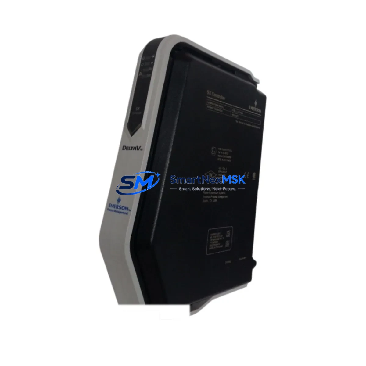
EMERSON A6500-CC Retrofit-Ready DCS Communication Card: Seamless Compatibility and Legacy System Upgrade
The EMERSON A6500-CC is a DCS Communication Card engineered for direct retrofit integration into EMERSON A6500 Series distributed control systems. As industrial facilities face increasing pressure to modernize aging control infrastructure without full system replacement, the A6500-CC provides a validated, cost-effective upgrade path that preserves existing rack architecture, terminal wiring, and control logic while delivering improved communication reliability and protocol support.
Whether you are replacing a failed card in an active production environment, upgrading a legacy A6500 control cabinet, or migrating communication protocols to meet current plant standards, the A6500-CC is designed to minimize engineering rework and reduce unplanned downtime. Its compatibility with the A6500 Series backplane and I/O bus means that in most retrofit scenarios, no mechanical modifications to the control cabinet are required.
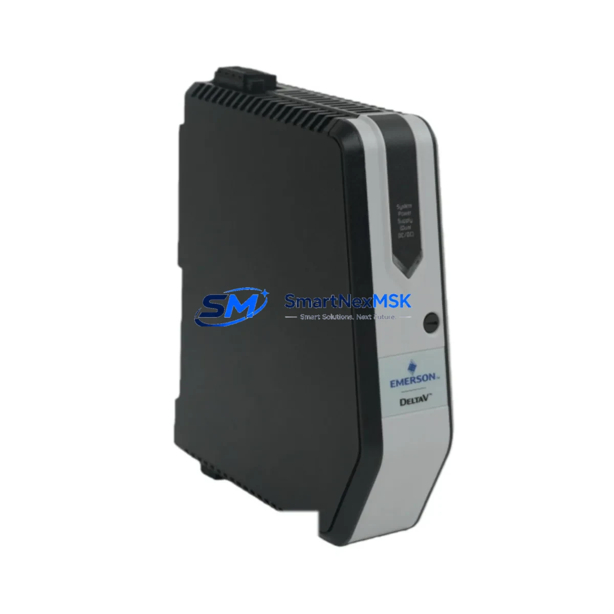
This card is commonly deployed alongside the EMERSON A6500-PS power supply module, which must be verified for adequate capacity before installation — particularly when adding communication-intensive modules to an existing rack. Engineers should confirm that the total current draw across all installed modules does not exceed the rated output of the A6500-PS to avoid instability during commissioning.
Upgrade Compatibility Table
| Parameter | Details |
|---|---|
| Compatible Series | EMERSON A6500 Series DCS |
| Backplane Interface | A6500 Series standard backplane bus |
| Communication Protocols | HART, Modbus RTU, proprietary EMERSON DCS bus (verify firmware revision) |
| Installation Type | Direct slot replacement — no rack modification required |
| Terminal Wiring | Compatible with existing A6500 Series terminal block layouts |
| Module Address | Configurable via DIP switch or engineering workstation software |
| Replacement Recommendation | Verify firmware version on host controller before swapping |
| Commissioning Note | Re-download I/O configuration after installation; verify HMI tag mapping |
| Warranty | 12-Month Warranty — covers manufacturing defects and functional failure |
Retrofit Planning for Existing Automation Systems
Successful retrofit of the A6500-CC into an existing control system requires a structured pre-installation review. Begin by auditing the current rack configuration: confirm the slot position, verify that the A6500 Series backplane supports the communication card in the target slot, and document the existing module address assignments to avoid conflicts with other installed cards such as the A6500-AI analog input module or the A6500-AO analog output module.
Terminal wiring compatibility is a critical checkpoint. The A6500-CC uses the same terminal block footprint as its predecessor, but engineers should verify field cable labeling against the original loop drawings before disconnecting any wiring. In systems where the A6500-DI digital input module or A6500-DO digital output module shares a common marshalling cabinet, it is advisable to photograph all terminal connections before removal.
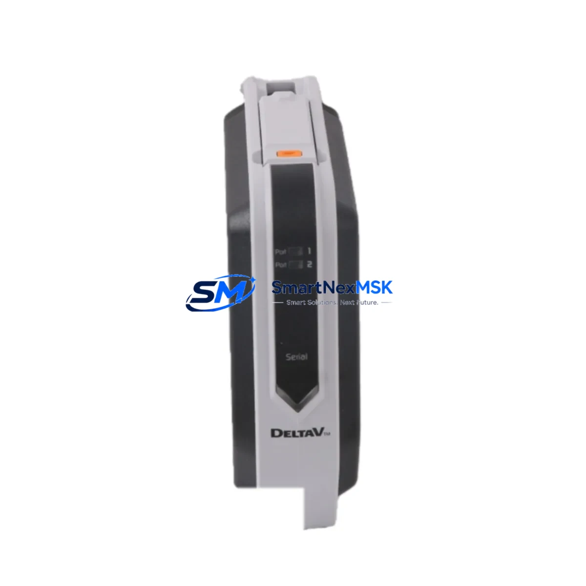
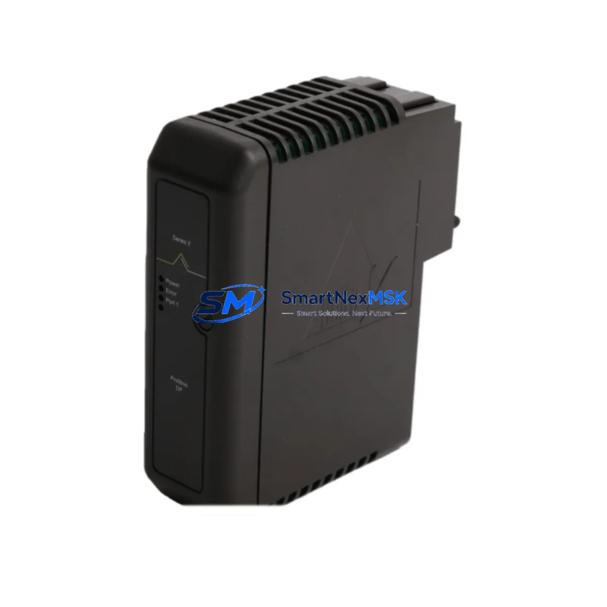
Communication link verification is equally important. If the existing system uses a legacy proprietary EMERSON DCS communication bus, confirm that the A6500-CC firmware revision is compatible with the host controller — typically an EMERSON DeltaV controller or an equivalent A6500 Series master station. In facilities migrating from older serial Modbus RTU links to HART-enabled field devices, the A6500-CC supports this protocol transition without requiring a separate communication gateway.
For systems that include an EMERSON A6500-RM remote I/O module or an A6500-CM communication master module in the same rack, module address conflicts must be resolved in the engineering workstation before the new card is powered on. The EMERSON DeltaV Explorer or equivalent configuration tool should be used to assign the correct node address and verify that the I/O map reflects the updated hardware configuration.
HMI screen updates are often overlooked during communication card replacements. If the plant uses an EMERSON DeltaV Operate HMI or a third-party SCADA system connected via OPC, verify that all tag references associated with the replaced card remain valid after the swap. In some cases, a partial tag re-import or faceplate update may be required to restore full display functionality.
Finally, confirm that the programming cable — typically an EMERSON PCCU cable or equivalent RS-232/USB adapter — is available on-site for any required firmware updates or configuration downloads during commissioning.
Downtime Control During System Migration
Minimizing production downtime during a communication card retrofit requires careful sequencing of activities. Where possible, pre-configure the A6500-CC on a bench workstation before bringing it to the field. Load the correct firmware, assign the module address, and verify communication parameters against the plant’s control system documentation before the scheduled maintenance window begins.
During the swap, place the affected control loop in manual mode at the DCS operator station to prevent automatic control actions from triggering while the card is offline. If the system supports hot-standby redundancy through a paired A6500-CC or a redundant communication path, activate the standby path before removing the primary card to maintain continuous field device communication.
After installation, perform a structured power-on sequence: energize the rack, confirm the card’s status LEDs indicate normal operation, and execute a communication link test from the engineering workstation before returning the loop to automatic control. Document the as-found and as-left configuration states for the plant’s maintenance records. This approach consistently reduces retrofit-related downtime to under two hours for single-card replacements in A6500 Series systems.
Retrofit Support FAQ
Q: Is the A6500-CC a direct drop-in replacement for the original EMERSON A6500 Series communication card?
A: Yes, in the majority of A6500 Series rack configurations, the A6500-CC is a direct slot replacement. Verify the firmware revision of your host controller and confirm the module address assignment before installation to ensure seamless integration.
Q: What wiring changes are required when installing the A6500-CC?
A: In most cases, no wiring changes are required. The A6500-CC uses the same terminal block layout as the original card. However, always verify field cable connections against the original loop drawings before disconnecting any terminals.
Q: How do I verify communication compatibility before commissioning?
A: Use the EMERSON engineering workstation software to perform a communication link test after installation. Confirm that the module address does not conflict with other installed cards, and verify that the HMI tag mapping reflects the updated hardware configuration.
Q: What does the 12-month warranty cover?
A: The 12-month warranty covers manufacturing defects and functional failure under normal operating conditions. Each unit undergoes pre-shipment functional testing to verify communication link integrity, I/O response, and power consumption within specification before dispatch.
© 2026 SMARTNEXMSK. All rights reserved.
Original Source: https://smartnexmsk.com
Contact: sales@smartnexmsk.com | +86 18259474341