EMERSON PR6423/014-111 CON031 Retrofit-Ready Proximity Sensor for PR6423 Series Control Systems
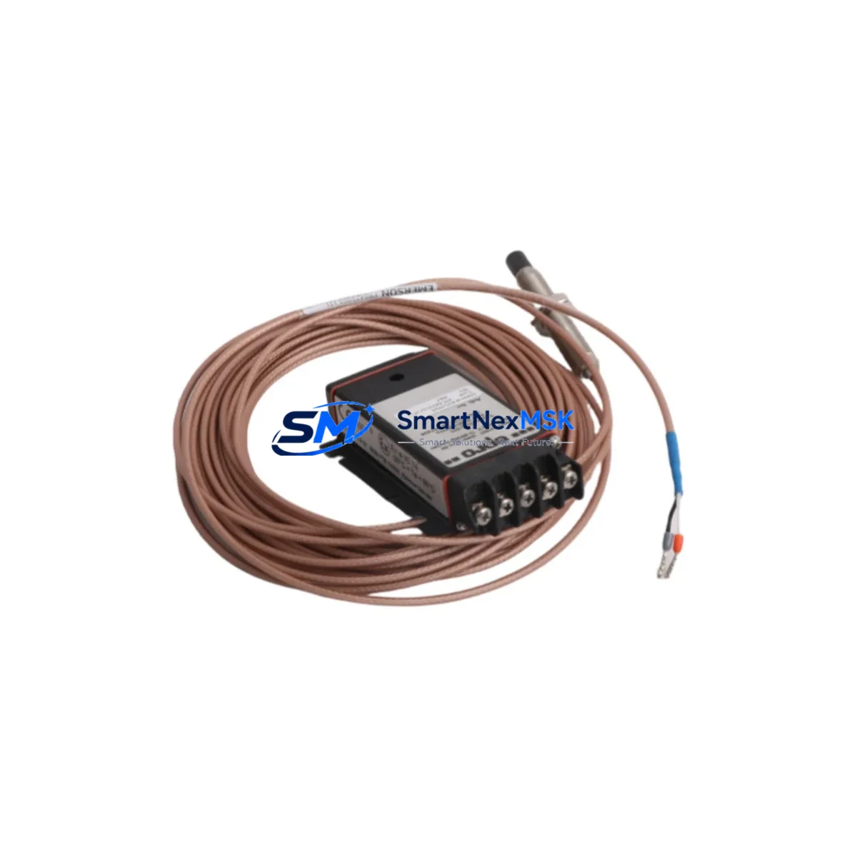
The EMERSON PR6423/014-111 CON031 is a high-precision eddy current proximity sensor engineered for seamless integration into existing PR6423 Series vibration monitoring and machinery protection systems. Designed to serve as a direct retrofit replacement for aging or discontinued sensor assemblies, this unit supports smooth migration from legacy Bently Nevada 3300 Series and 7200 Series monitoring platforms to current-generation EMERSON machinery protection architectures. Whether you are upgrading a turbine control cabinet, replacing a worn proximity probe in a compressor train, or restoring a mothballed production line, the PR6423/014-111 CON031 delivers the dimensional accuracy, signal linearity, and environmental resilience required for continuous industrial operation.
This sensor is fully compatible with the CON031 extension cable and driver system, and integrates directly with the PR6423 Series driver modules without requiring firmware changes or signal conditioning adapters. Engineers undertaking a retrofit should verify the existing cable length and connector pinout against the PR6423/014-111 specification sheet before installation. The probe tip diameter, thread pitch, and mounting bracket dimensions are identical to the original factory configuration, eliminating the need for mechanical rework on the bearing housing or proximity probe holder.
Upgrade Compatibility Table
| Parameter | PR6423/014-111 CON031 | Legacy / Replaced Model |
|---|---|---|
| Sensor Type | Eddy Current Proximity | Eddy Current Proximity |
| Probe Tip Diameter | 14 mm | 14 mm (compatible) |
| Thread Standard | M14 × 1.0 | M14 × 1.0 |
| Cable / Extension | CON031 (5 m standard) | CON021 / CON011 (adapter may be required) |
| Driver Compatibility | PR6423 Series Driver | 3300 XL / 7200 Series (signal check required) |
| Output Signal | −24 VDC, 200 mV/mil | −24 VDC, 200 mV/mil |
| Communication Protocol | Analog (4–20 mA / voltage) | Analog (compatible) |
| Mounting Interface | Standard proximity probe holder | Direct fit, no rework required |
| Installation Requirement | Gap setting: 1.0–1.5 mm nominal | Re-gap required after swap |
| Commissioning Note | Verify OK/NOT OK LED on driver module | Recalibrate after replacement |
| Warranty | 12 Months | — |
Retrofit Planning for Existing Automation Systems
A successful retrofit of the PR6423/014-111 CON031 into an operating plant begins well before the maintenance window opens. The first step is a full audit of the existing proximity probe system: document the current probe model, extension cable part number, driver module revision, and the rack or chassis into which the driver is installed. In most PR6423 Series installations, the driver module is housed in a 3500 Series rack or a legacy 3300 rack, and the rack backplane connector pinout must be confirmed before the new sensor is energized.
Power supply capacity is a critical checkpoint. The PR6423/014-111 CON031 draws its bias voltage from the driver module, which in turn is powered by the rack’s internal −24 VDC bus. If the existing power supply module — such as a 3500/15 Power Supply or a standalone DIN-rail 24 VDC unit — is already operating near its rated output current, adding a replacement sensor without a load audit can cause voltage droop and false NOT OK alarms across adjacent channels. Always measure the available headroom on the power rail before committing to a multi-channel sensor swap.
Terminal wiring on the driver module follows the standard three-wire proximity probe convention: probe (white), extension cable shield (drain), and driver output to the monitor card. When replacing the CON031 extension cable alongside the probe, label each conductor at both ends before disconnection. In older installations where the junction box or conduit seal has degraded, inspect the cable jacket for moisture ingress, which is a common cause of intermittent gap voltage errors that are frequently misdiagnosed as probe failures.
For plants running EMERSON Ovation DCS or a third-party DCS such as Honeywell Experion or ABB 800xA, the proximity probe signal feeds into a vibration monitor card — typically a 3500/42M Proximitor/Seismic Monitor or a 3500/40M Proximitor Monitor — before the conditioned 4–20 mA or relay output reaches the DCS I/O module. After the physical swap, confirm that the monitor card’s gap voltage reading falls within the −10 to −18 VDC OK range. If the plant uses a Modbus RTU or PROFIBUS DP gateway to relay vibration data to the control room HMI, verify that the tag address and engineering unit scaling in the gateway configuration have not been altered during the maintenance outage.
HMI faceplate verification is a step that is often deferred but should be completed before the machine is returned to service. On a GE iFIX, Wonderware InTouch, or EMERSON DeltaV Live HMI, confirm that the proximity probe channel tag is reading correctly, that the alarm setpoints for high vibration and danger levels match the machinery OEM specification, and that the trend historian is logging the new data without a gap. If the plant uses a Bently Nevada System 1 condition monitoring platform, re-synchronize the probe configuration in the System 1 database after the replacement to ensure that the waveform and spectrum data are correctly attributed to the new sensor serial number.
I/O expansion considerations arise when a retrofit is combined with a broader control system upgrade. If the plant is simultaneously migrating from a 3300 Series rack to a 3500 Series rack, the number of available monitor channels may change, requiring a review of the I/O map and the PLC or DCS tag list. In such cases, the PR6423/014-111 CON031 can be installed in the new rack while the old rack remains energized, allowing a channel-by-channel cutover that minimizes exposure to simultaneous multi-point outages.
Downtime Control During System Migration
Minimizing unplanned downtime during a proximity sensor retrofit requires a structured cutover plan that preserves the original control logic and alarm architecture throughout the transition. Before any wiring is disturbed, export a full backup of the monitor rack configuration using Bently Nevada’s Rack Configuration Software or the equivalent tool for your platform. This backup captures channel assignments, alarm setpoints, transducer scale factors, and relay output logic — all of which must be restored identically on the replacement hardware.
Where the process cannot be fully shut down, a hot-standby approach is recommended: install the PR6423/014-111 CON031 in a parallel channel of the same 3500 rack, verify its gap voltage and signal output against the live channel, and then perform a controlled switchover at a low-load moment. This technique is particularly effective in compressor and turbine applications where a brief sensor outage would otherwise trigger a protective trip and an unplanned production loss.
Program logic compatibility should be confirmed at the PLC or DCS level. If the vibration monitor relay output feeds a safety PLC — such as a Triconex Tricon or a Rockwell Automation GuardLogix — verify that the input module’s signal range and the safety function’s proof-test interval are unaffected by the sensor change. Document the as-found and as-left gap voltage readings, the OK/NOT OK status at energization, and the first-scan alarm status in the maintenance record to support future audits and insurance inspections.
Field commissioning should conclude with a bump test or a slow-roll vibration check to confirm that the new sensor is tracking shaft motion correctly. Compare the waveform on the System 1 or equivalent condition monitoring platform against the historical baseline to confirm that no offset or scaling error has been introduced. Only after this verification is complete should the machine be returned to full-speed operation and the maintenance work order closed.
Retrofit Support FAQ
Q1: Is the PR6423/014-111 CON031 a direct drop-in replacement for the PR6423/014-110 CON021?
A: The probe body dimensions and thread pitch are identical, making the physical installation a direct fit. However, the CON031 extension cable uses a different connector than the CON021. You will need to either replace the extension cable or use a CON021-to-CON031 adapter. Verify the total system length (probe + extension) against the driver module’s specified range before energizing.
Q2: What gap voltage should I expect after installation, and how do I adjust it?
A: With the PR6423/014-111 CON031 installed at the nominal 1.0–1.5 mm air gap, the driver module should read between −10 VDC and −18 VDC on the gap voltage test point. Adjust the probe axial position using the locknut on the proximity probe holder until the reading falls within this range. The driver’s OK LED will illuminate when the gap is within the acceptable window.
Q3: Can this sensor be used with a third-party vibration monitor that is not part of the EMERSON 3500 Series?
A: Yes, provided the third-party monitor is designed for use with −24 VDC-biased eddy current probes and accepts the 200 mV/mil (7.87 mV/μm) scale factor. Confirm the input impedance and bias voltage range of the third-party driver before connecting the PR6423/014-111 CON031, as mismatched bias voltage can damage the probe tip or produce non-linear output.
Q4: What does the 12-month warranty cover, and is pre-shipment testing performed?
A: Every PR6423/014-111 CON031 unit is function-tested prior to shipment, including gap voltage linearity verification and OK/NOT OK threshold confirmation. The 12-month warranty covers manufacturing defects and component failures under normal operating conditions. It does not cover damage resulting from incorrect gap setting, reverse polarity connection, or installation in environments exceeding the sensor’s rated temperature and IP rating. Warranty claims are processed through sales@smartnexmsk.com with the original order reference and a fault description.
© 2026 SMARTNEXMSK. All rights reserved.
Original Source: https://smartnexmsk.com
Contact: sales@smartnexmsk.com | +86 18259474341