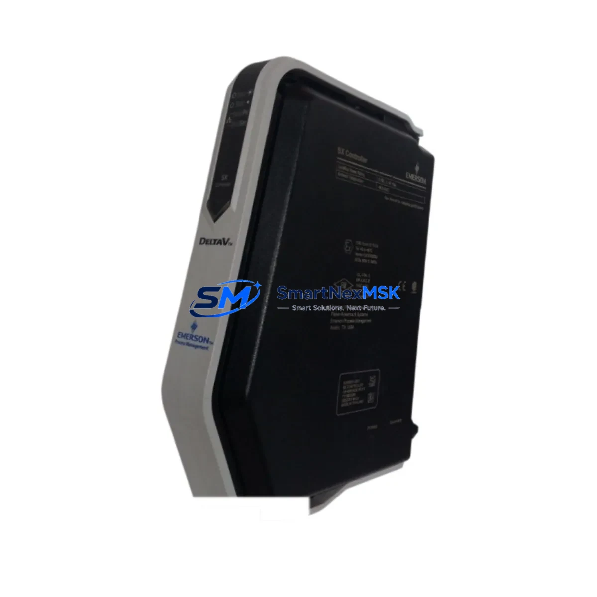
EMERSON PR9268/201-100 Maintenance-Ready Spare for PR9268 Automation
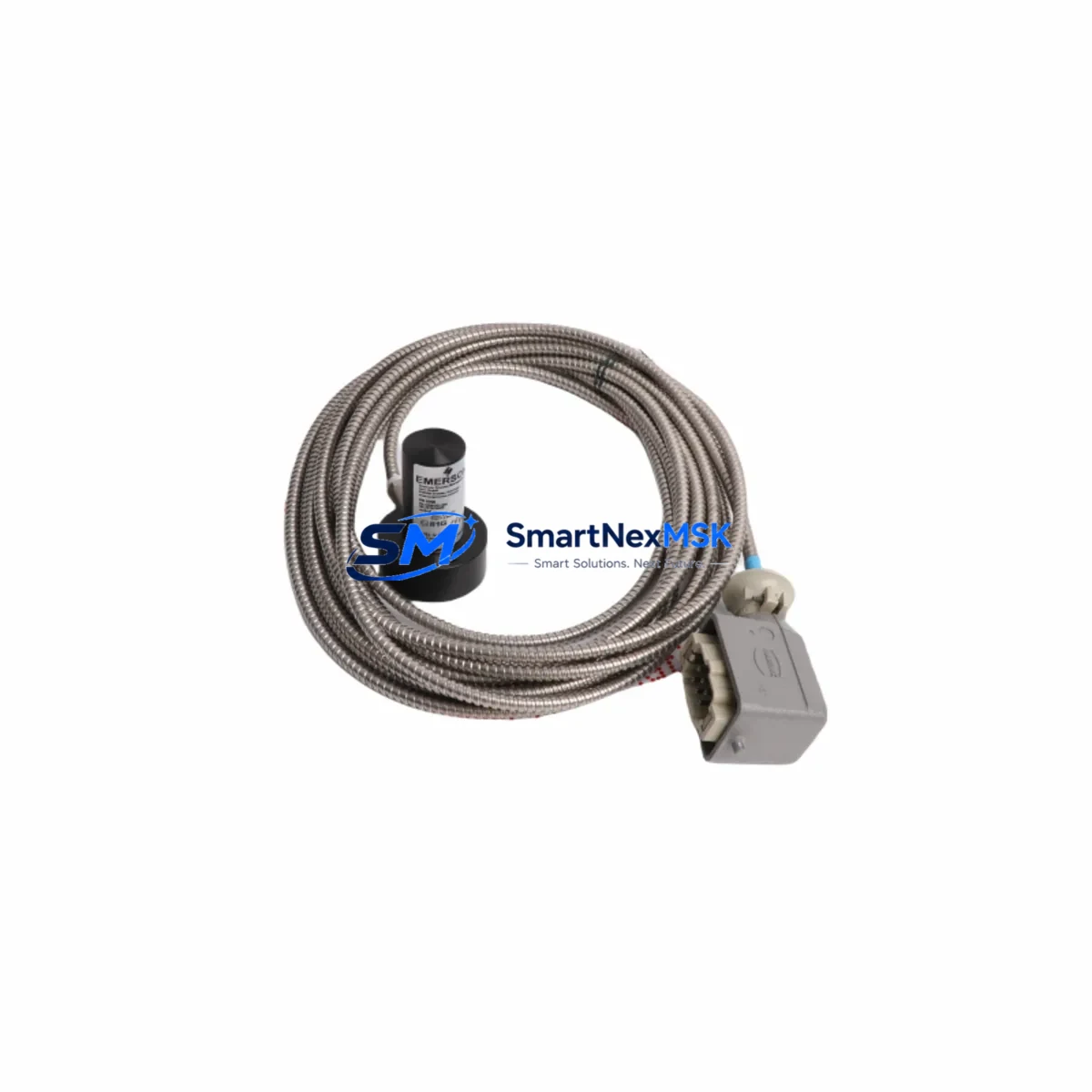
The EMERSON PR9268/201-100 is an original electrodynamic velocity sensor engineered for continuous vibration monitoring in rotating machinery and critical industrial automation systems. As a direct maintenance-ready spare within the PR9268 Series, this unit is purpose-built to support rapid field replacement, minimize unplanned downtime, and sustain the integrity of condition monitoring loops in turbines, compressors, pumps, and motor-driven equipment.
For maintenance engineers managing aging control architectures or planning scheduled overhauls, the PR9268/201-100 represents a proven, drop-in replacement that eliminates the compatibility risk associated with third-party alternatives. Each unit is tested before shipment, supplied with a 12-month warranty, and backed by long-term spare parts support — making it a reliable choice for both emergency procurement and strategic inventory stocking.
Procurement engineers sourcing this part for MRO (Maintenance, Repair & Operations) inventories will find the PR9268/201-100 readily available with short lead times, traceable origin documentation, and consistent supply from authorized industrial channels. Whether you are replacing a failed sensor during an emergency shutdown or pre-positioning spares ahead of a planned turnaround, this component delivers the specification accuracy and supply reliability that industrial operations demand.
Spare Maintenance Table
| Parameter | Specification |
|---|---|
| Part Number / SKU | PR9268/201-100 |
| Brand | EMERSON |
| Series | PR9268 |
| Product Type | Electrodynamic Velocity Sensor |
| Measurement Parameter | Vibration Velocity (mm/s or in/s) |
| Sensing Principle | Electrodynamic (moving coil) |
| Output Signal | Analog voltage proportional to velocity |
| Frequency Range | Typically 10–1000 Hz (series standard) |
| Mounting | Threaded stud / flange mount |
| Housing / Protection | Stainless steel, IP65 or better |
| Operating Temperature | -40°C to +120°C (typical industrial range) |
| Country of Origin | Germany (DE) |
| Weight | 740 g |
| Compatibility | PR9268 Series monitoring systems; EMERSON CSI, AMS, and compatible vibration monitoring panels |
| Application Environment | Rotating machinery, turbines, compressors, pumps, fans, motors |
| Maintenance Recommendation | Inspect cable integrity and connector seating at each planned shutdown; replace sensor if sensitivity drift exceeds ±5% |
| Warranty | 12 Months from date of shipment |
| Pre-Shipment Testing | Yes — functional and output verification |
Maintenance Planning for Continuous Operation
When replacing the PR9268/201-100 in the field, a thorough inspection of the surrounding measurement chain is essential to ensure the replacement restores full system accuracy and prevents repeat failures. Maintenance engineers should treat this replacement as an opportunity to audit the entire vibration monitoring loop.
Begin by inspecting the sensor cable assembly and armored extension cable connecting the PR9268/201-100 to the monitoring panel — cable insulation degradation and connector corrosion are leading causes of signal drift that are often misdiagnosed as sensor failure. Check the terminal blocks and cable glands at the junction box for tightness and moisture ingress, particularly in outdoor or high-humidity installations.
At the monitoring panel or control cabinet, verify the condition of the vibration monitoring module or transmitter card that receives the sensor signal — in EMERSON and compatible systems, this is often a dedicated channel card within a PR6423, PR9376, or equivalent rack-mount monitor. Confirm that the input impedance and signal conditioning settings match the PR9268/201-100 output characteristics.
For installations where the velocity signal feeds into a PLC or DCS analog input module, check the AI channel calibration and scaling parameters after sensor replacement to ensure the engineering unit conversion (mm/s or in/s) remains accurate. If the system uses a signal isolator or signal conditioner between the sensor and the control system, inspect it for output drift or power supply issues — a failing isolator can mask a healthy sensor or corrupt a good signal.
Review the power supply module feeding the monitoring rack: unstable supply voltage is a common root cause of erratic vibration readings. Check fuse holders and circuit protection fuses on the sensor supply circuit. In multi-channel monitoring cabinets, also inspect adjacent sensor channels — if one PR9268-series sensor has failed, others in the same installation environment may be approaching end of service life.
Where the vibration monitoring system interfaces with a safety relay or trip relay module, verify that the relay setpoints and response times are correctly configured after the sensor swap. Finally, if the plant uses a portable vibration analyzer or handheld data collector for route-based monitoring alongside the fixed system, recalibrate the reference baseline for this measurement point after installing the new PR9268/201-100 to maintain trend data integrity.
For older installations where the PR9268/201-100 is part of a legacy condition monitoring system, consider pre-positioning a second unit as a cold standby spare in the local maintenance store. Long-term supply continuity for this series is supported, but having an on-site spare eliminates lead time risk during emergency shutdowns.
Site Replacement Workflow
Step 1 — Isolation & Safety: Follow site LOTO (Lockout/Tagout) procedures. Isolate the sensor circuit at the terminal block or junction box before disconnecting the PR9268/201-100. Do not disconnect under live signal conditions.
Step 2 — Documentation: Record the existing sensor orientation, cable routing, and connector pin assignment before removal. Photograph the installation if possible. Note the current vibration baseline reading from the monitoring system for post-installation comparison.
Step 3 — Mechanical Removal: Unthread or unbolt the sensor from its mounting stud or flange. Inspect the mounting surface for corrosion, thread damage, or contamination. Clean and re-tap threads if necessary before installing the replacement unit.
Step 4 — Installation of PR9268/201-100: Mount the new sensor to the specified torque. Reconnect the cable assembly, ensuring correct polarity and secure connector seating. Verify cable strain relief is intact.
Step 5 — Signal Verification: Restore power to the monitoring circuit. Confirm the output signal is within the expected range at the monitoring panel or DCS/PLC input. Compare the live reading against the pre-removal baseline — a significant deviation may indicate a mounting or cable issue rather than sensor fault.
Step 6 — System Handover: Update the maintenance management system (CMMS) with the replacement date, new serial number, and post-installation readings. Reset any latched alarms in the monitoring system. Confirm with the control room that the vibration channel is back in service before releasing the equipment to operations.
This workflow is applicable whether the PR9268/201-100 is replacing an identical failed unit or substituting an older PR9268-series variant. The PR9268/201-100 is designed for backward compatibility within the PR9268 platform, reducing the engineering effort required for like-for-like replacements in legacy systems.
Spare Parts Support FAQ
Q1: What is the warranty coverage for the PR9268/201-100?
Each PR9268/201-100 supplied by SMARTNEXMSK carries a 12-month warranty from the date of shipment. The warranty covers manufacturing defects and functional failures under normal operating conditions. All units undergo functional and output verification testing before dispatch.
Q2: Can the PR9268/201-100 replace older PR9268-series variants in existing installations?
Yes. The PR9268/201-100 is designed for compatibility within the PR9268 Series platform. For installations using earlier PR9268 variants, verify the cable connector type and mounting thread specification before installation. In most cases, the replacement is direct and requires no modification to the monitoring system configuration.
Q3: How should I manage PR9268/201-100 inventory for a multi-unit plant?
For plants operating multiple rotating machines with PR9268-series sensors, a minimum stock of one to two units per critical machine train is recommended. Sensors in high-temperature or high-vibration environments should be inspected at each planned shutdown and replaced on a condition-based or time-based interval (typically 3–5 years depending on operating severity). Centralized spare parts storage with CMMS tracking ensures traceability and prevents expired stock from entering service.
Q4: What documentation is provided with each shipment?
Each PR9268/201-100 is shipped with a test report confirming pre-shipment functional verification, a packing list, and origin documentation. Certificate of conformance and additional traceability documents can be provided upon request. Contact sales@smartnexmsk.com for specific documentation requirements prior to order placement.
© 2026 SMARTNEXMSK. All rights reserved.
Original Source: https://smartnexmsk.com
Contact: sales@smartnexmsk.com | +86 18259474341