EUPEC BSM200GB170DLC Retrofit-Ready IGBT Module for DLC Series Control Systems
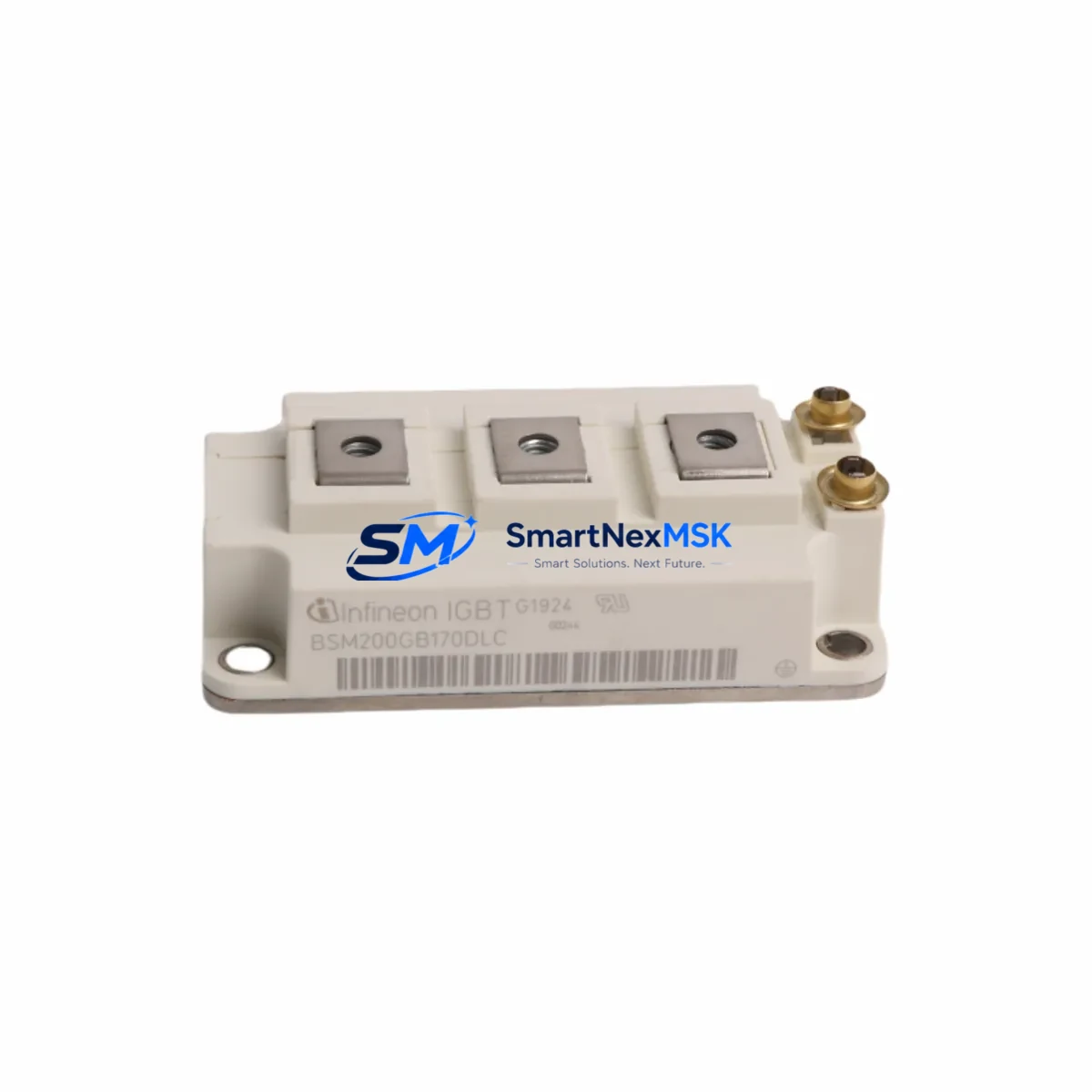
The EUPEC BSM200GB170DLC is a 200A / 1700V half-bridge IGBT power module engineered for seamless retrofit integration into legacy DLC Series drive and inverter platforms. As original EUPEC DLC-generation modules approach end-of-life and spare parts become increasingly scarce, the BSM200GB170DLC provides a verified drop-in upgrade path that preserves existing wiring layouts, baseplate mounting dimensions, and gate-drive signal compatibility — minimizing engineering rework and unplanned downtime during system modernization.
Industrial facilities operating aging frequency converters, medium-voltage motor drives, traction inverters, and regenerative braking systems will find the BSM200GB170DLC particularly valuable when the original module is no longer available through standard distribution channels. The module’s IHV (Isolated High Voltage) package format aligns with standard 62mm half-bridge footprints, allowing direct substitution without PCB modification in most DLC-generation power stacks.
Upgrade Compatibility Table
| Parameter | BSM200GB170DLC Specification | Retrofit Notes |
|---|---|---|
| Collector Current (IC) | 200 A | Verify original module rating; derate if ambient >70°C |
| Blocking Voltage (VCES) | 1700 V | Suitable for 690 V AC bus applications |
| Package / Footprint | 62mm half-bridge (IHV) | Direct baseplate swap; confirm heatsink flatness ≤ 50 µm |
| Gate Drive Voltage | +15 V / −8 V | Compatible with standard EUPEC gate-drive boards |
| Isolation Voltage | 4000 Vrms | No additional isolation barrier required |
| Thermal Interface | Baseplate (Cu) | Re-apply thermal compound; torque to 3 N·m per datasheet |
| Communication Compatibility | N/A (power stage) | Upper-level PROFIBUS / PROFINET control logic unaffected |
| Replacement Recommendation | 1:1 for DLC Series half-bridge positions | Confirm phase-leg pairing with matched VCE(sat) values |
| Commissioning Focus | Gate-drive timing, desaturation threshold | Re-verify short-circuit protection after installation |
| Warranty | 12 Months | Covers manufacturing defects; full pre-shipment functional test |
Retrofit Planning for Existing Automation Systems
A successful BSM200GB170DLC retrofit begins well before the module arrives on-site. Engineers should first audit the existing power cabinet to confirm DC bus voltage, capacitor bank condition, and snubber circuit integrity. In many DLC-era drive cabinets, the gate-drive board — often a dedicated EUPEC driver card or a compatible third-party equivalent — must be inspected for aging optocouplers and gate resistors before the new IGBT module is energized.
When the drive system interfaces with a Siemens S7-300 or S7-400 PLC via PROFIBUS DP, the control program’s fault-response logic should be reviewed to ensure that the new module’s slightly improved switching characteristics do not trigger nuisance overcurrent trips. If the system uses a CP 342-5 or CP 443-5 communications processor for PROFIBUS coordination, no protocol changes are required — the BSM200GB170DLC operates transparently at the power stage level.
For systems where I/O expansion is part of the modernization scope, this is an ideal time to audit ET 200S or ET 200M distributed I/O racks connected to the drive control cabinet. Replacing aging SM 321 digital input modules or SM 331 analog input modules alongside the IGBT swap reduces the risk of secondary failures after recommissioning. Similarly, if the HMI panel — typically a Siemens TP 177 or OP 177 — displays drive status via OPC or MPI, verify that the screen’s fault-code library reflects the updated module’s protection thresholds.
Backplane and rack integrity should not be overlooked. In older S7-400 installations, the UR2 universal rack or ER2 expansion rack may show signs of connector wear; cleaning and re-seating all module connectors before powering up the retrofitted drive prevents intermittent communication faults. If the system includes a PS 407 power supply module, confirm its output capacity is sufficient to support any additional I/O or communication modules added during the upgrade.
Programming cable access is essential during commissioning. A PC adapter USB or MPI/PROFIBUS adapter should be on hand to connect STEP 7 or TIA Portal for online monitoring of the drive’s fault buffer and to perform a function test of the new IGBT module under partial load before returning the line to full production speed.
Downtime Control During System Migration
Minimizing production interruption is the primary concern for any IGBT module replacement in a running facility. The recommended approach is a staged swap: schedule the physical module exchange during a planned maintenance window, pre-stage the BSM200GB170DLC alongside all required consumables (thermal compound, torque wrench, replacement gate-drive fuses), and prepare a rollback plan in case the first energization reveals an unexpected system interaction.
Before de-energizing the drive, capture a full backup of the PLC program using STEP 7 or TIA Portal, and photograph all terminal wiring on the gate-drive board and DC bus connections. This documentation protects against wiring errors during reassembly and provides a reference if the HMI fault history needs to be cross-checked post-commissioning. DC bus capacitors must be fully discharged — confirmed with a calibrated voltmeter — before any module handling begins.
After installation, perform a low-voltage gate-drive test before applying full DC bus voltage. Confirm that the desaturation detection circuit responds correctly and that the top and bottom switch timing is symmetric. Gradually ramp the output frequency under no-load conditions before connecting the motor, monitoring module case temperature and gate-drive supply current throughout. A properly executed retrofit typically returns the line to full production within a single shift, with the 12-month warranty providing assurance against latent manufacturing defects.
Retrofit Support FAQ
Q1: Is the BSM200GB170DLC a direct replacement for all DLC Series half-bridge positions?
In most DLC-generation inverter and drive platforms using the standard 62mm IHV package, the BSM200GB170DLC is a 1:1 physical and electrical replacement. Always verify the original module’s VCES and IC ratings against the drive’s design specification before installation.
Q2: What commissioning steps are required after installation?
Re-apply thermal interface material, torque baseplate fasteners to the manufacturer’s specification, verify gate-drive supply voltages (+15 V / −8 V), and perform a no-load energization test. Check the PLC fault buffer for any new diagnostic codes and confirm motor current symmetry across all phases before returning to production.
Q3: How is wiring compatibility confirmed before the swap?
Document all existing gate-drive signal connections, DC bus terminal assignments, and auxiliary voltage wiring before disassembly. The BSM200GB170DLC uses the same terminal layout as the original DLC Series module, so no rewiring is required in standard applications. Confirm terminal torque values from the module datasheet.
Q4: What does the 12-month warranty cover?
Every BSM200GB170DLC unit undergoes pre-shipment functional testing covering gate-drive response, isolation integrity, and static VCE(sat) measurement. The 12-month warranty covers manufacturing defects identified under normal operating conditions. Warranty claims are supported by our technical team at sales@smartnexmsk.com.
© 2026 SMARTNEXMSK. All rights reserved.
Original Source: https://smartnexmsk.com
Contact: sales@smartnexmsk.com | +86 18259474341