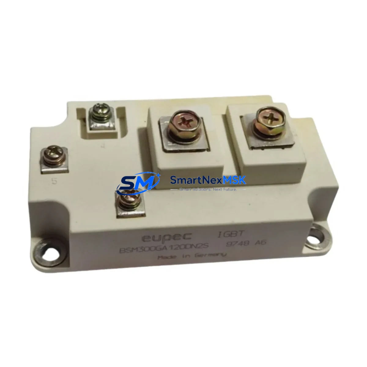
EUPEC BSM300GA120DN2S Spare FF Series Automation: Spare Replacement & Industrial Downtime Risk Control
The EUPEC BSM300GA120DN2S is a 300A / 1200V full-bridge IGBT power module from the FF Series, widely deployed in industrial variable-frequency drives (VFDs), medium-voltage converters, UPS systems, and servo amplifiers. As a maintenance-ready original spare, the BSM300GA120DN2S is engineered to deliver direct drop-in replacement capability, minimizing unplanned downtime and restoring production continuity with confidence.
For maintenance engineers managing aging drive cabinets or planning scheduled overhauls, sourcing a verified original BSM300GA120DN2S — rather than a counterfeit or ungraded substitute — is critical. This module ships fully tested, with dynamic switching parameters verified against EUPEC factory specifications, and is backed by a 12-month warranty covering electrical performance and structural integrity.
Spare Maintenance Table
| Parameter | Specification |
|---|---|
| Part Number | BSM300GA120DN2S |
| Brand / Manufacturer | EUPEC (Infineon Technologies) |
| Series | FF Series (Full-Bridge IGBT) |
| Collector Current (IC) | 300 A |
| Collector-Emitter Voltage (VCES) | 1200 V |
| Configuration | Full-Bridge (H-Bridge), 6-pack equivalent |
| Gate-Emitter Voltage (VGES) | ±20 V |
| Operating Junction Temperature | –40°C to +150°C |
| Thermal Resistance (Rth j-c) | Typically 0.05–0.08 K/W per switch |
| Package / Footprint | FF Series baseplate module, industry-standard mounting |
| Compatibility | Direct replacement for BSM300GA120DN2, BSM300GA120DLC, and equivalent FF-package IGBT modules |
| Application Environment | VFDs, servo drives, medium-voltage converters, UPS, traction inverters |
| Origin | Germany (EUPEC / Infineon) |
| Mounting | Baseplate with M6 screw terminals; thermal paste application required |
| Warranty | 12 Months — covers electrical performance and structural integrity |
| Pre-shipment Testing | Dynamic switching, leakage current, gate threshold, and thermal resistance verified |
Maintenance Planning for Continuous Operation
When replacing the BSM300GA120DN2S in a drive cabinet or converter rack, a disciplined maintenance engineer does not stop at the IGBT module itself. The surrounding electrical circuit must be inspected and, where necessary, replaced in the same maintenance window to prevent repeat failures and ensure system reliability.
Begin with the DC bus capacitor bank — electrolytic capacitors adjacent to the IGBT module are subject to voltage stress and thermal aging. If the BSM300GA120DN2S failed due to overcurrent or short-circuit, the capacitors may have absorbed transient energy and should be tested for ESR and capacitance before recommissioning. Similarly, inspect the gate driver board (often a dedicated PCB such as the EUPEC SKYPER 32 PRO or equivalent driver module) for burned gate resistors, damaged optocouplers, or degraded bootstrap capacitors — a faulty gate driver is a common root cause of IGBT destruction.
Check the DC bus fuses and fast-acting semiconductor fuses (e.g., Bussmann 170M series or equivalent) installed in series with the module. These are sacrificial protection components and must be replaced after any IGBT failure event, even if they appear visually intact. Inspect the NTC thermistor or temperature sensor mounted on the module baseplate — if the original module overheated, the thermistor may have drifted out of calibration, causing the drive controller to misread thermal status.
For systems using a Siemens SINAMICS, ABB ACS, or Schneider Altivar drive platform, verify that the control board firmware has not logged persistent fault codes that indicate upstream issues — overcurrent (OC), overvoltage (OV), or ground fault (GF) faults should be investigated before energizing the replacement module. If the drive uses a PLC I/O module for enable/disable signaling (such as a Siemens ET 200SP digital output module or equivalent), confirm that the output signal integrity is within specification to avoid false triggering.
In converter cabinets with multiple IGBT positions, consider replacing all modules in the same phase leg or bridge arm simultaneously — mismatched aging characteristics between an old module and a new BSM300GA120DN2S can cause current imbalance and premature failure. Also inspect the busbars, laminated bus connections, and terminal torque on the module’s collector and emitter terminals; loose connections generate localized heating that degrades the new module’s solder joints over time.
For systems with a communication module (PROFIBUS DP, PROFINET, or Modbus RTU interface card) connected to the drive, verify that the fieldbus address and parameter set are correctly restored after the drive is powered down for module replacement. Finally, review the HMI or SCADA alarm history to identify whether the BSM300GA120DN2S failure was preceded by recurring thermal warnings, which may indicate inadequate cooling airflow, a blocked heat sink, or a failing cooling fan that must also be serviced.
Site Replacement Workflow
Step 1 — Isolation & Lockout/Tagout: De-energize the drive, discharge the DC bus capacitors to below 50 V (use a calibrated voltmeter), and apply LOTO procedures before opening the cabinet.
Step 2 — Document the existing configuration: Photograph terminal wiring, record gate driver board connections, and note the torque values on the module mounting screws. This is essential for restoring the system to its original state.
Step 3 — Remove the failed module: Unscrew the baseplate mounting bolts (typically M6, 4–6 Nm torque), disconnect gate and emitter signal leads, and carefully lift the module from the heat sink. Clean residual thermal compound from the heat sink surface using isopropyl alcohol.
Step 4 — Prepare the replacement BSM300GA120DN2S: Apply a thin, uniform layer of high-performance thermal interface material (e.g., Dow Corning TC-5026 or equivalent) to the module baseplate. Do not use excessive compound — a 0.1–0.15 mm bond line is optimal for this package size.
Step 5 — Install and torque: Position the module on the heat sink, hand-tighten all mounting screws in a cross pattern, then torque to the manufacturer’s specification (typically 4–6 Nm for M6 screws). Reconnect gate driver leads, observing polarity markings.
Step 6 — Pre-power verification: Before energizing, perform a static gate-emitter resistance check and confirm no short circuit between collector and emitter. Verify gate driver supply voltage is within specification.
Step 7 — Commissioning: Power up the drive at reduced load, monitor thermal performance for the first 30 minutes of operation, and confirm no fault codes are generated. Log the replacement in the maintenance record with date, technician, and module serial number.
This workflow is compatible with legacy systems using older FF-package IGBT modules, allowing the BSM300GA120DN2S to serve as a long-term replacement that extends system life without requiring drive controller modifications.
Spare Parts Support FAQ
Q1: Is the BSM300GA120DN2S a direct replacement for the BSM300GA120DN2 or BSM300GA120DLC?
Yes. The BSM300GA120DN2S is electrically and mechanically compatible with the BSM300GA120DN2 and BSM300GA120DLC in the same FF Series baseplate package. The “S” suffix denotes an enhanced version with improved short-circuit ruggedness. No drive parameter changes are required for a direct swap in most VFD and converter applications. Always verify gate driver voltage and resistance settings match the new module’s gate charge specifications before commissioning.
Q2: How is the module tested before shipment?
Every BSM300GA120DN2S unit undergoes pre-shipment electrical testing covering: collector-emitter leakage current (ICES), gate threshold voltage (VGE(th)), on-state voltage drop (VCE(sat)), and static gate-emitter resistance. Modules that fail any parameter are rejected. A test report is available upon request. Packaging includes anti-static foam and moisture barrier bag with desiccant to prevent humidity damage during transit.
Q3: What is the warranty coverage and what does it include?
All BSM300GA120DN2S units are covered by a 12-month warranty from the date of shipment. The warranty covers electrical performance failure under normal operating conditions, including open-circuit or short-circuit failure of any IGBT or diode cell within the module. It does not cover damage resulting from incorrect installation, overvoltage events beyond rated VCES, or operation without adequate thermal management. Warranty claims are processed within 5 business days of receiving the returned unit.
Q4: Can you support long-term or blanket orders for ongoing maintenance programs?
Yes. For maintenance engineers managing multi-site facilities or OEM service programs, we support scheduled blanket orders with reserved stock allocation. Minimum order quantities for reserved stock programs start at 5 units. Lead time for standard orders is 3–7 business days; expedited same-week shipping is available for critical downtime situations. Contact our technical sales team to discuss consignment stock arrangements or annual supply agreements.
© 2026 SMARTNEXMSK. All rights reserved.
Original Source: https://smartnexmsk.com
Contact: sales@smartnexmsk.com | +86 18259474341