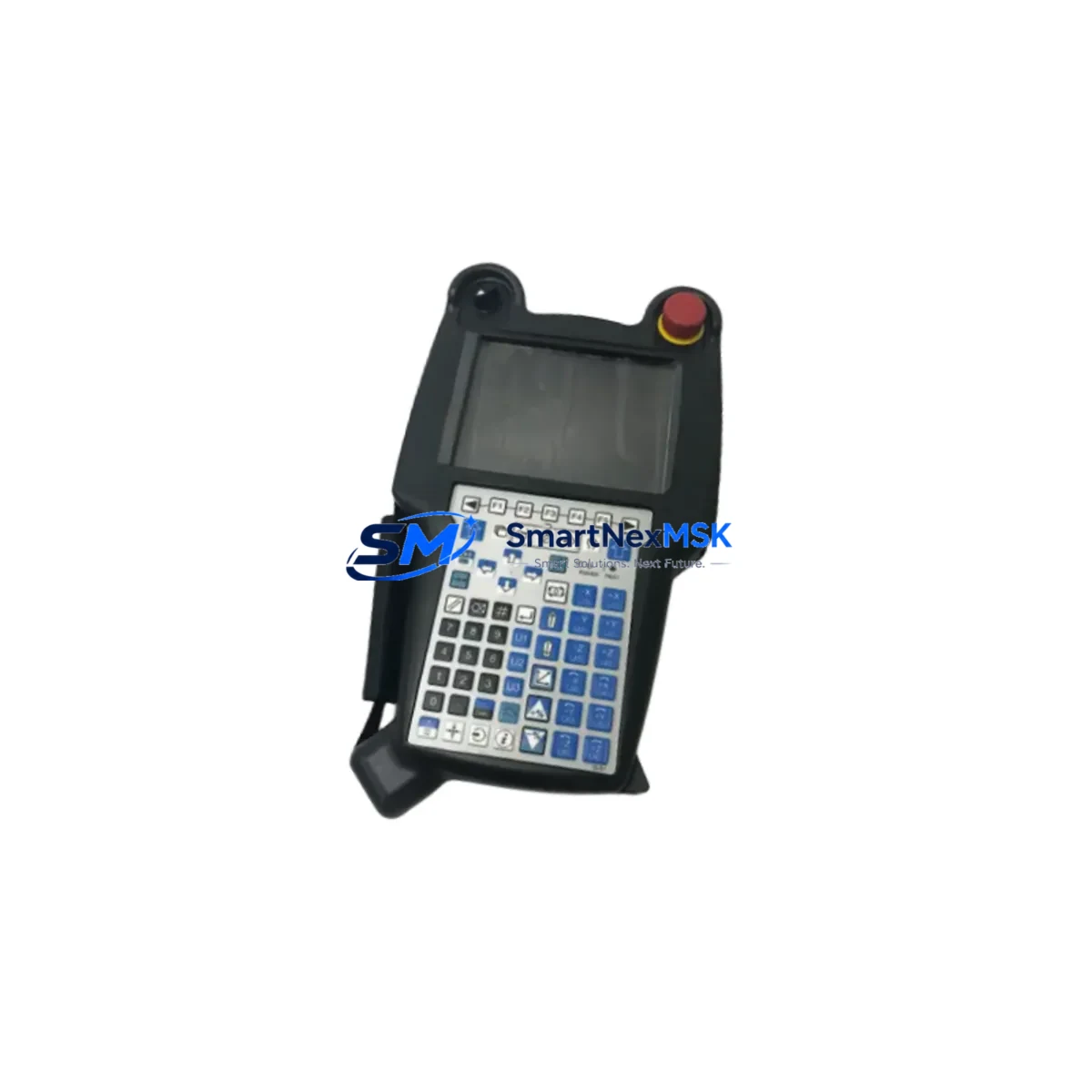
FANUC A05B-2518-C200: Retrofit-Ready I-Pendant for Series 30i/31i/32i Control Systems
The FANUC A05B-2518-C200 is a high-reliability I-Pendant (Intelligent Pendant) designed for seamless integration into FANUC Series 30i, 31i, and 32i CNC control systems. As legacy machine tools age and OEM support windows close, the A05B-2518-C200 has become one of the most sought-after retrofit components for production facilities seeking to extend the operational life of their existing CNC infrastructure without committing to a full machine replacement. Whether you are upgrading a worn-out pendant on a multi-axis machining center, replacing a damaged unit on a turning cell, or migrating from an older FS-16i or FS-18i platform to the 30i architecture, this pendant delivers the compatibility, durability, and field-proven performance that industrial engineers demand.
Sourced directly from verified supply channels and subjected to pre-shipment functional testing, every A05B-2518-C200 unit shipped by SMARTNEXMSK is backed by a 12-month warranty covering hardware defects and operational failures under normal industrial use conditions.
Upgrade Compatibility Table
| Parameter | Details |
|---|---|
| Compatible Control Series | FANUC Series 30i-A, 30i-B, 31i-A, 31i-A5, 31i-B, 32i-A, 32i-B |
| Connector Interface | Standard FANUC pendant cable connector (JD1A/JD1B port on CNC unit) |
| Display | 8.4-inch color LCD with touch panel |
| Communication Protocol | FANUC proprietary serial (HSSB / Ethernet optional) |
| Installation Requirement | Direct drop-in; no mechanical modification required for standard 30i cabinets |
| Replacement Compatibility | Replaces A05B-2518-C200, A05B-2518-C201, A05B-2518-C202 (verify suffix) |
| Retrofit Recommendation | Confirm CNC software version (Series 30i-B requires ≥ V8.0); update PMC ladder if migrating from 16i/18i |
| Commissioning Focus | Pendant enable signal, E-stop circuit continuity, axis jog confirmation, macro variable display check |
| Warranty | 12 months from shipment date; covers hardware defects under normal operating conditions |
Retrofit Planning for Existing Automation Systems
Successful integration of the A05B-2518-C200 into a legacy or transitional CNC environment requires careful pre-installation planning. Engineers undertaking a retrofit should begin by auditing the existing control cabinet layout. In most Series 30i installations, the CNC unit — typically a FANUC 30i-B or 31i-A5 main control board — is mounted in a standard FANUC control cabinet alongside the servo amplifier modules (such as the αiSV series) and spindle amplifier (αiSP series). Confirming that the cabinet’s 24VDC power supply rail has sufficient capacity to support the pendant’s power draw is a critical first step; the A05B-2518-C200 draws approximately 1.5A at 24VDC, and any undersized PSU should be replaced or supplemented before installation.
Terminal wiring is the next checkpoint. The pendant connects via the standard FANUC pendant cable assembly to the JD1A or JD1B port on the CNC control unit. Technicians should inspect the cable for insulation damage, verify pin continuity with a multimeter, and confirm that the enable switch circuit (a dual-channel safety input) is correctly wired to the machine’s safety relay module. In facilities that use a FANUC Panel i or a third-party operator panel, the pendant’s enable signal must be mapped correctly in the PMC (Programmable Machine Controller) ladder program — a step that is frequently overlooked during rushed retrofits and can result in axis motion inhibit faults.
For sites migrating from older FANUC FS-16i or FS-18i controls, the transition to the 30i architecture introduces changes in the PMC address map and macro executor environment. Before swapping the pendant, engineers should export and archive the existing PMC ladder, CNC parameters (all 9000+ parameter blocks), and any custom macro programs (O9000–O9999 range). The FANUC SRAM backup function, accessible via the boot screen of the 30i-B, should be used to create a full memory image. This backup protects against data loss during the hardware swap and provides a restore point if commissioning reveals unexpected behavior.
I/O expansion is another common requirement in retrofit projects. Many older machining centers rely on FANUC I/O Link modules — such as the A03B-0819-C001 I/O Unit-MODEL A or the compact A20B-2002-0520 I/O board — to interface with machine-side sensors, solenoids, and limit switches. When upgrading to the 30i platform, engineers should verify that the existing I/O Link topology is compatible with the new CNC’s I/O Link II protocol, and add FANUC I/O Link II slave units where necessary. Similarly, if the machine uses a FANUC αi Pulse Coder for axis feedback, confirming that the encoder cable pinout matches the 30i servo interface is essential before powering up.
HMI screen migration is a detail that is easy to underestimate. Custom operator screens built for the FS-16i using FANUC Macro Executor (FAPT MACRO) may require recompilation or screen layout adjustments when displayed on the A05B-2518-C200’s 8.4-inch LCD. The FANUC Picture function (used for custom screen creation on 30i) uses a different development environment than older systems, so plan for HMI validation time in the project schedule. Communication links — particularly any DNC (Direct Numerical Control) connections using RS-232C or Ethernet — should be re-established and tested with the new pendant in place, as the 30i’s embedded Ethernet port may require IP address reconfiguration and firewall rule updates on the factory network.
Downtime Control During System Migration
Minimizing unplanned downtime is the primary operational concern during any CNC pendant replacement or control system upgrade. The recommended approach is to complete all pre-installation tasks — parameter backup, PMC export, cable inspection, and spare parts staging — during scheduled maintenance windows or planned production gaps, so that the physical swap can be completed in a single shift.
Before disconnecting the existing pendant, power down the CNC in the correct sequence: first disable the servo drives (confirm the αiSV amplifier charge lamps are extinguished), then power off the CNC control unit, and finally isolate the main cabinet breaker. This sequence prevents residual charge from damaging the pendant connector or the JD1A port on the control board. After installing the A05B-2518-C200, restore power in reverse order and monitor the CNC boot sequence for any parameter mismatch alarms (typically Alarm 910 or 935 on the 30i platform).
To protect original program logic, never clear SRAM during the swap unless specifically required. If the CNC displays a memory error after the pendant replacement, use the previously created SRAM backup to restore parameters and PMC data before attempting manual re-entry. Keeping the original PMC ladder intact ensures that machine-side interlocks, axis travel limits, and spindle orientation logic remain functional from the first power-on after the retrofit.
Field continuity is maintained by keeping a spare A05B-2518-C200 unit on-site for high-utilization machines. SMARTNEXMSK maintains in-stock inventory of this pendant and can support same-day dispatch for urgent replacement requirements, reducing mean time to repair (MTTR) for critical production assets.
Retrofit Support FAQ
Q1: Is the A05B-2518-C200 a direct drop-in replacement for the A05B-2518-C201 or C202 suffix variants?
A: The C200, C201, and C202 suffix variants differ primarily in cable length and minor hardware revisions. In most installations, the C200 is functionally interchangeable with C201 and C202 for Series 30i/31i/32i controls, but you should confirm the cable length requirement and verify the CNC software version before ordering. Contact our technical team with your machine model and current pendant part number for a definitive compatibility confirmation.
Q2: What commissioning steps are required after installing the A05B-2518-C200?
A: After installation, power on the CNC and verify that no pendant-related alarms appear (check Alarm 910, 935, and DS0300 series). Confirm the enable switch function by testing axis jog in each direction. Verify E-stop circuit continuity using the machine’s safety relay diagnostic screen. Check that all custom macro screens display correctly and that DNC communication links are re-established. Document the commissioning results for your maintenance records.
Q3: Does the A05B-2518-C200 support FANUC’s HSSB (High Speed Serial Bus) interface?
A: The standard A05B-2518-C200 uses FANUC’s proprietary serial pendant interface. HSSB connectivity is a separate option typically associated with the PC-based operator panel configurations. For standard 30i/31i/32i CNC cabinets using the built-in pendant port, the A05B-2518-C200 connects directly without additional interface hardware.
Q4: What does the 12-month warranty cover, and how is a warranty claim processed?
A: The 12-month warranty covers hardware defects and component failures under normal industrial operating conditions. It does not cover physical damage caused by incorrect wiring, overvoltage, or mechanical impact. To initiate a warranty claim, contact SMARTNEXMSK with your order number, a description of the fault, and any relevant CNC alarm codes. We will arrange return shipping and provide a replacement or repaired unit within the agreed service timeline.
© 2026 SMARTNEXMSK. All rights reserved.
Original Source: https://smartnexmsk.com
Contact: sales@smartnexmsk.com | +86 18259474341