FANUC A06B-6240-H209 Retrofit-Ready Dual-Axis Servo Amplifier for AiSV Series Control Systems
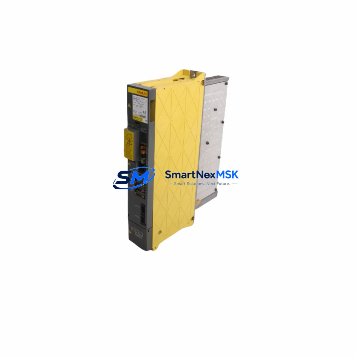
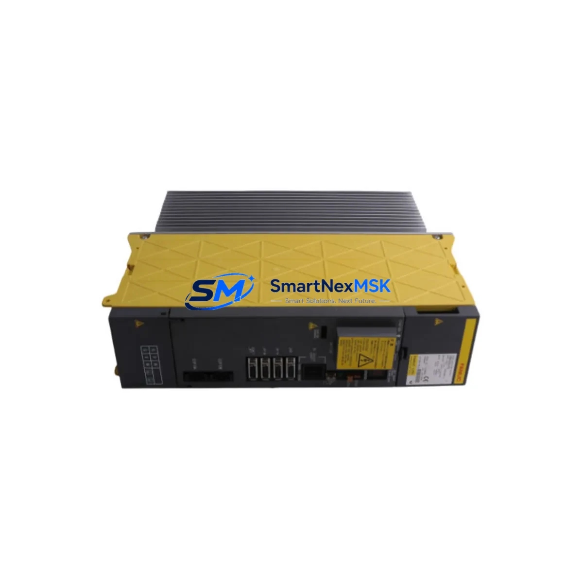
The FANUC A06B-6240-H209 is a dual-axis Alpha i Servo (AiSV) amplifier rated at 80A/80A, designed for high-performance CNC and motion control applications across FANUC 30i, 31i, 32i, and 0i-D/F series platforms. As legacy servo drive units reach end-of-life or become unavailable through standard supply channels, the A06B-6240-H209 serves as a verified retrofit-ready replacement for older AiSV and AiSP series amplifier configurations, enabling production lines to resume operation with minimal downtime and without requiring full controller replacement.
This unit is sourced from authorized industrial surplus channels, fully tested prior to shipment, and backed by a 12-month warranty covering manufacturing defects and functional failures under normal operating conditions. Stock is maintained for immediate dispatch to support urgent breakdown recovery and planned maintenance windows.
Upgrade Compatibility Table
| Parameter | A06B-6240-H209 (This Unit) | Notes / Retrofit Guidance |
|---|---|---|
| Amplifier Type | Dual-Axis AiSV | Replaces single or dual-axis AiSV/AiSP units where axis count matches |
| Rated Output Current | 80A / 80A (Axis 1 / Axis 2) | Verify motor nameplate current does not exceed amplifier rating |
| Compatible Controllers | FANUC 30i-A/B, 31i-A/B, 32i-A/B, 0i-D, 0i-F | FSSB (Fiber-optic Servo Serial Bus) interface required on CNC side |
| Backplane / Rack Interface | FANUC Alpha i Series Servo Rack | Confirm rack slot width and power bus connector alignment before installation |
| Communication Protocol | FSSB (High-speed serial) | Not compatible with older HSSB or analog command interfaces without adapter |
| DC Bus Input | Via PSM (Power Supply Module) | Confirm A06B-6200 or A06B-6220 series PSM capacity covers combined axis load |
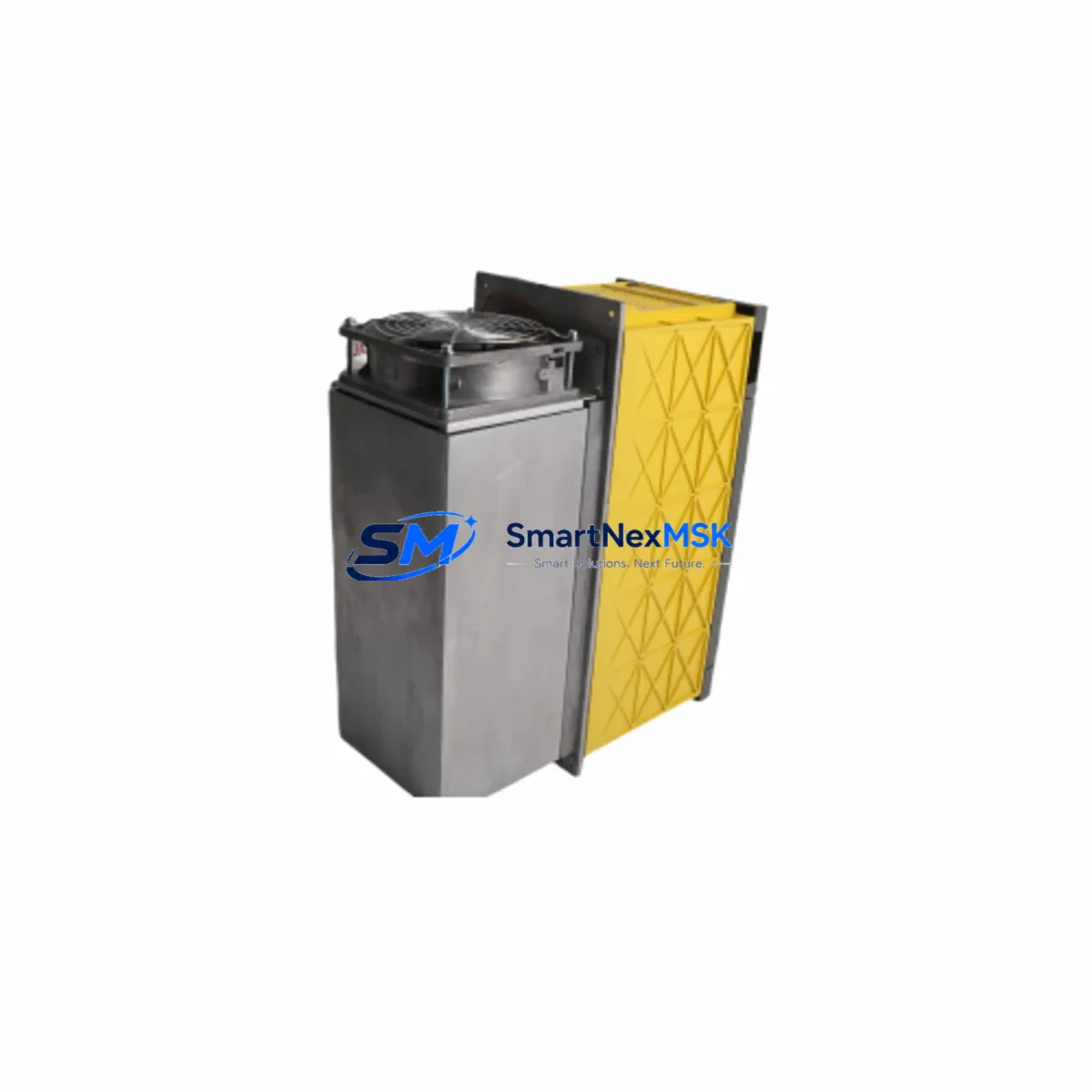
| Cooling Method | Forced air (internal fan) | Ensure cabinet airflow meets FANUC thermal specification; clean filters before installation |
| Replacement Recommendation | Direct swap for same-series AiSV 80/80 units | Parameter backup (F-ROM/SRAM) required before swap; restore after installation |
| Commissioning Focus | Axis address, servo parameters, motor ID | Re-run servo tuning if motor type differs from original configuration |
| Warranty | 12 Months | Covers functional failure under normal industrial operating conditions |
Retrofit Planning for Existing Automation Systems
Replacing a servo amplifier in a live production environment requires careful pre-work to avoid extended downtime and protect existing program logic. Before removing the failed or obsolete unit, engineers should perform a full parameter backup using FANUC BOOT screen or a programming pendant, capturing all axis parameters, servo gain settings, and spindle data stored in F-ROM and SRAM. If the machine uses a FANUC Series 30i or 31i controller, the CNC parameter file should also be exported via the memory card slot or RS-232C port using a programming cable such as the FANUC A02B-0120-C196 or equivalent data transfer cable.
The A06B-6240-H209 mounts into the standard Alpha i servo rack alongside other amplifier modules. In a typical multi-axis cabinet, this unit may share a rack with additional AiSV or AiSP amplifiers handling other axes, as well as a spindle amplifier such as the A06B-6200-H011 or A06B-6220-H011 for spindle motor control. The DC bus is supplied by a Power Supply Module (PSM) — commonly an A06B-6200-H011 or A06B-6220-H015 — and engineers must verify that the PSM’s rated output capacity covers the combined peak demand of all connected servo and spindle amplifiers after the replacement unit is added.
Terminal wiring for the motor power connector (CX5X/CX6X) and the feedback connector (JF1/JF2) must be confirmed against the original wiring diagram. FANUC Alpha i series servo motors — such as those in the αiF, αiS, or βiS families — use a standardized feedback connector pinout, but cable lengths and shield grounding practices should be verified to prevent noise-induced encoder faults (Alarm 360 or 361 series). If the retrofit involves migrating from an older Beta i amplifier or a standalone drive to the Alpha i platform, the motor feedback cable may require an adapter or full replacement.
For systems that include FANUC I/O Link or DeviceNet I/O expansion modules, such as the A03B-0819-C001 I/O Link module or distributed I/O units connected via the I/O Link i protocol, engineers should confirm that the I/O address map remains intact after the amplifier swap. In some configurations, the servo amplifier’s axis address is set via rotary switch or parameter, and an incorrect address will cause the CNC to report a servo alarm at power-on. The axis address must match the FSSB configuration stored in the CNC parameters.
If the machine uses a FANUC iHMI or an older FANUC Series 0i operator panel, the HMI screen layout and alarm message files do not typically require modification for a like-for-like amplifier replacement. However, if the retrofit involves upgrading from a 0i-C to a 0i-F platform as part of a broader modernization, the HMI ladder program and PMC (Programmable Machine Controller) logic may require review to ensure compatibility with the new CNC’s I/O signal mapping. In such cases, the FANUC LADDER-III programming software is used to review and transfer PMC programs.
Downtime Control During System Migration
Minimizing unplanned downtime during a servo amplifier replacement begins with preparation, not installation. Before the maintenance window opens, the replacement A06B-6240-H209 should be bench-tested using a compatible servo motor and a known-good PSM to confirm the unit powers up, passes self-diagnostics, and responds to a basic JOG command. This pre-shipment functional test is performed on every unit dispatched from our facility, and the test record is available upon request.
During the swap, the original amplifier’s FSSB fiber-optic cables — connecting the CNC to the first amplifier in the chain, and daisy-chaining to subsequent axes — should be labeled and photographed before disconnection. FSSB chain order directly affects axis assignment, and reversing the connection order will cause axis mismatch alarms. The replacement unit should be inserted into the same rack slot, with the fiber-optic cables reconnected in the original sequence.
After power-on, the CNC will perform an FSSB initialization sequence. If the amplifier’s axis parameters were correctly restored from backup, the system should reach the emergency stop ready state within the normal boot cycle. Engineers should monitor the servo amplifier’s LED status indicators during initialization — a steady green LED on both axis channels confirms normal operation, while a flashing or red LED indicates a parameter or hardware fault requiring further diagnosis.
To protect original program logic throughout the migration, the CNC’s part programs, tool offset tables, work coordinate data, and macro variables should be backed up to a CF card or USB memory device before any hardware is disturbed. This ensures that even in the event of an unexpected SRAM battery failure during the swap — a known risk when cabinet power is interrupted — the program data can be fully restored without manual re-entry.
Retrofit Support FAQ
Q1: Is the A06B-6240-H209 a direct replacement for the A06B-6240-H206 or A06B-6240-H203?
A: The H209 variant is rated at 80A/80A and is not directly interchangeable with lower-current variants such as the H206 (60A/60A) or H203 (40A/40A) without verifying that the connected servo motors’ rated current falls within the H209’s operating range. Uprating to a higher-current amplifier is generally acceptable if the motor current is within range, but the servo parameters (particularly the current loop gain settings) may require adjustment. Contact our technical team with your motor model numbers for a compatibility confirmation before ordering.
Q2: What wiring changes are required when replacing a failed AiSV amplifier with the A06B-6240-H209?
A: For a like-for-like replacement within the same AiSV 80/80 rating, no wiring changes are required. The motor power connectors (CX5X, CX6X), feedback connectors (JF1, JF2), and FSSB fiber-optic cables connect identically to the original unit. If the replacement involves a different amplifier generation or a different axis count configuration, terminal mapping should be verified against the FANUC Servo Amplifier Maintenance Manual (B-65285EN) before proceeding.
Q3: How is the unit tested before shipment, and what does the 12-month warranty cover?
A: Every A06B-6240-H209 unit is powered up and functionally tested on a dedicated servo test bench prior to dispatch. The test confirms DC bus charging, FSSB communication handshake, axis enable response, and absence of hardware alarms. The 12-month warranty covers functional failure attributable to manufacturing defects or component failure under normal industrial operating conditions. It does not cover damage resulting from incorrect installation, overvoltage events, or physical impact. Warranty claims are processed with a return authorization; replacement units are dispatched within 3 business days of fault confirmation.
Q4: Can this unit be used in a system being upgraded from FANUC Series 16i to Series 31i?
A: The A06B-6240-H209 is compatible with the FANUC 31i-A and 31i-B CNC platforms, which are the standard upgrade targets for legacy 16i systems. However, the 16i platform uses an older servo amplifier generation (Alpha series, not Alpha i), so the physical rack, PSM, and all amplifier modules must be replaced as part of the migration. The servo motors may be reused if they are Alpha i compatible (αiF or αiS series with Pulsecoder feedback), but this must be confirmed on a motor-by-motor basis. Our team can assist with a full bill-of-materials review for 16i-to-31i migration projects.
© 2026 SMARTNEXMSK. All rights reserved.
Original Source: https://smartnexmsk.com
Contact: sales@smartnexmsk.com | +86 18259474341