FANUC A20B-2004-038 Maintenance-Ready Spare for A20B Automation
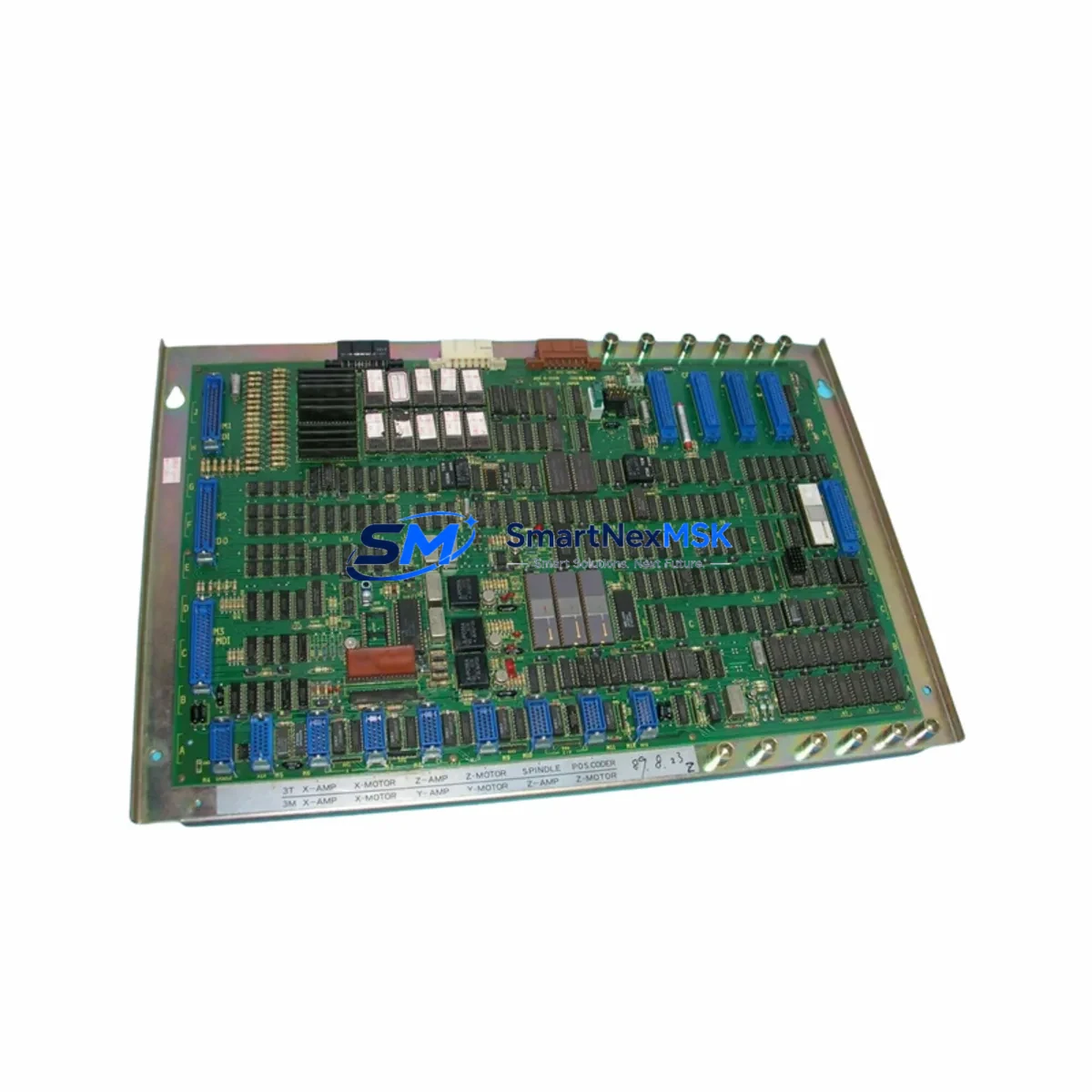
The FANUC A20B-2004-038 is a critical printed circuit board used across FANUC CNC control systems in the A20B series platform. For maintenance engineers managing aging CNC machining centers, grinding machines, or multi-axis turning systems, this board represents a high-priority spare that directly impacts machine uptime and production continuity. Unplanned failure of this PCB can halt an entire production line — making pre-stocked, tested replacements essential to any serious spare parts strategy.
This unit is sourced as an original FANUC spare, fully tested prior to shipment, and backed by a 12-month warranty. It is suitable for emergency replacement, scheduled overhaul, and long-term lifecycle extension of legacy FANUC control cabinets. Whether you are responding to an alarm code, conducting a planned shutdown inspection, or building a critical spare inventory for a multi-machine facility, the A20B-2004-038 is a board that should be on your shelf before you need it.
Spare Maintenance Table
| Part Number | A20B-2004-038 |
| Brand | FANUC |
| Series | A20B |
| Component Type | Printed Circuit Board (PCB) |
| Origin | Japan |
| Compatibility | FANUC CNC Series 0, 10, 11, 15, 16, 18, 21 and compatible A20B-series control cabinets |
| Typical Application | CNC machining centers, turning centers, grinding machines, multi-axis systems |
| Installation Environment | Industrial control cabinet, DIN rail or backplane mount |
| Operating Temperature | 0°C to 55°C (standard industrial range) |
| Pre-Shipment Testing | Functional test performed on all units before dispatch |
| Condition | Original spare / refurbished-to-spec (clearly stated per order) |
| Warranty | 12 Months |
| Lead Time | In-stock units ship within 1–3 business days |
| Maintenance Recommendation | Inspect capacitors, connectors, and solder joints during installation; verify axis alarms clear after swap |
Maintenance Planning for Continuous Operation
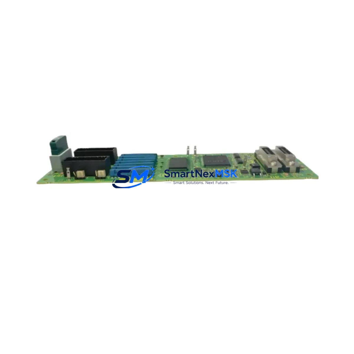
When replacing the A20B-2004-038 in a FANUC control cabinet, experienced maintenance engineers treat the board swap as an opportunity for a broader cabinet inspection. The PCB does not operate in isolation — it interfaces with the power supply unit (PSU), servo amplifier modules, I/O link boards, and the main CPU board. A failure in the A20B-2004-038 is often preceded or accompanied by degraded performance in adjacent components.
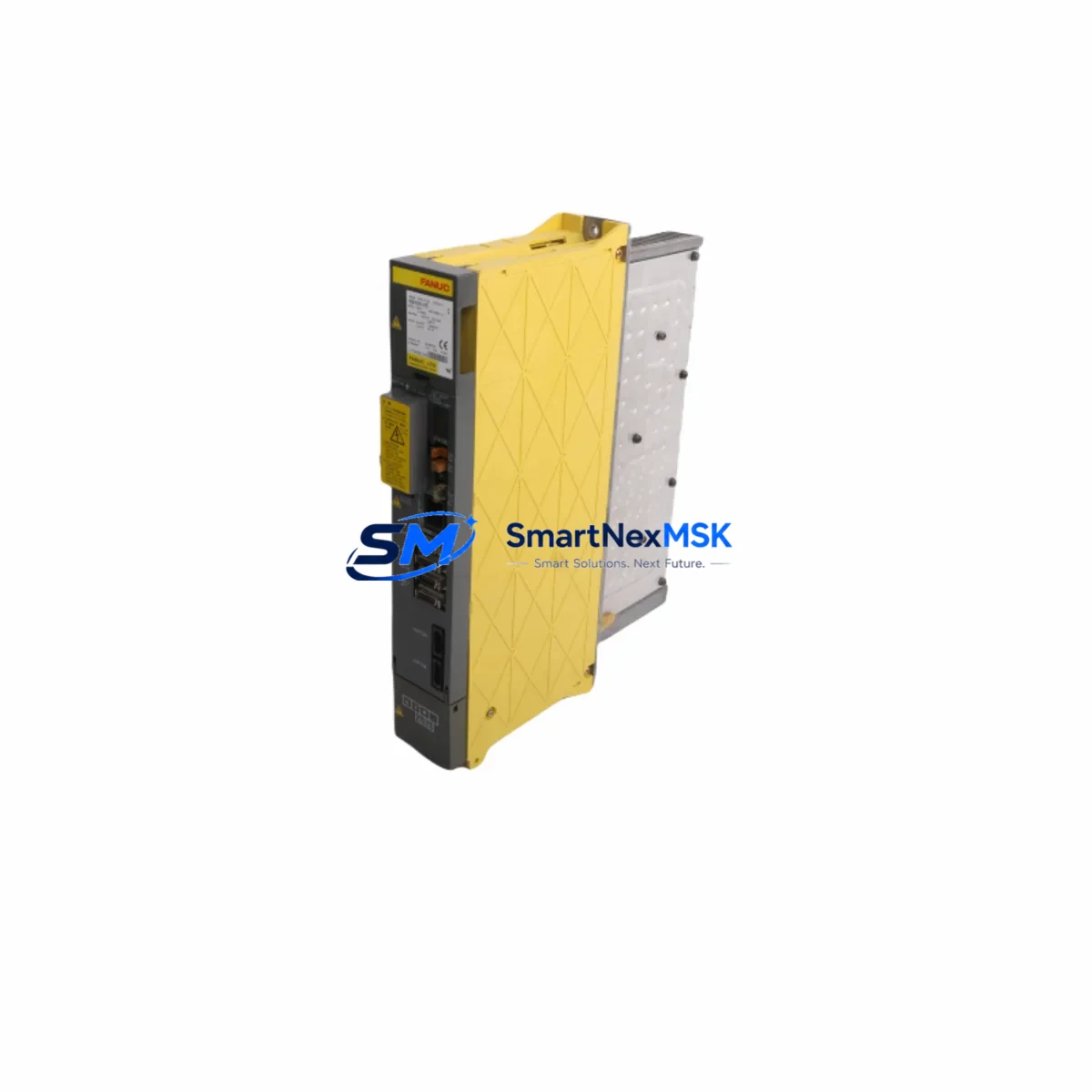
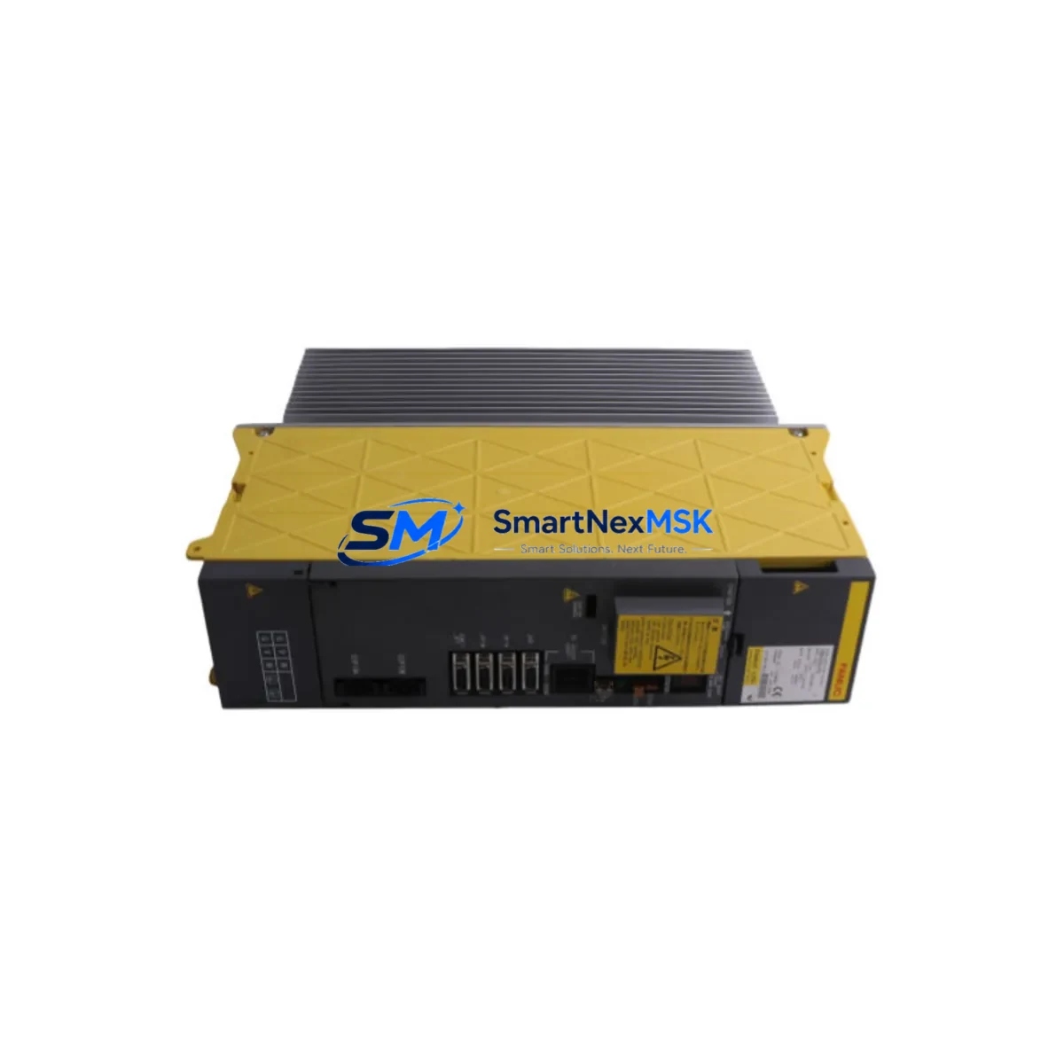
During a planned replacement, it is advisable to inspect the FANUC A16B series power supply board for capacitor bulge or output voltage drift, as an unstable power rail is a common root cause of PCB failure. The A20B-2001 and A20B-2002 series boards in the same rack should be visually inspected for burn marks, corrosion, or loose edge connectors. If the machine uses a FANUC Servo Amplifier (αi or βi series), verify that the DC bus voltage and regenerative brake resistor are within specification — excessive voltage spikes can damage control boards over time.
On the I/O side, check the FANUC I/O Module (A03B series) for proper signal continuity, especially if the machine has been experiencing intermittent axis faults or M-code execution errors. Terminal blocks and Phoenix Contact or Weidmüller-style screw terminals in the cabinet should be re-torqued, as vibration-induced loosening is a frequent cause of signal noise that stresses PCB components. If the system uses a FANUC PMC (Programmable Machine Controller) ladder program, back up the PMC data before the swap to avoid re-commissioning delays.
For facilities running older FANUC systems, consider stocking the A20B-2004-038 alongside the A20B-2004-0390 and A20B-2004-0391 variants, which are used in adjacent control configurations. A FANUC MDI/CRT unit or iHMI panel should also be on the inspection checklist — display faults are sometimes misdiagnosed as PCB failures. Additionally, fuse blocks and circuit breakers feeding the control cabinet should be tested for proper trip ratings, and any signal isolators or surge suppressors on encoder or spindle feedback lines should be verified for integrity.
Site Replacement Workflow
Step 1 — Fault Isolation: Record all active alarms on the FANUC operator panel. Cross-reference alarm codes with the FANUC maintenance manual to confirm the A20B-2004-038 is the suspected fault source before ordering or installing a replacement.
Step 2 — Safe Shutdown: Power down the CNC control following the machine builder’s lockout/tagout procedure. Allow the DC bus to discharge fully (minimum 5 minutes after power-off) before opening the control cabinet.
Step 3 — Board Removal: Document connector positions with photos before disconnecting. Label all cables. Remove the board carefully, avoiding static discharge — use an ESD wrist strap and anti-static mat.
Step 4 — Compatibility Verification: Confirm the replacement A20B-2004-038 matches the revision level of the removed board if the machine builder specifies a minimum revision. Check the board label and compare with the original.
Step 5 — Installation and Power-Up: Seat the replacement board firmly, reconnect all cables in documented order, and restore power. Monitor the FANUC boot sequence for alarm codes. Clear any battery alarms and verify axis reference positions.
Step 6 — Functional Test: Run a dry-cycle test program to confirm all axes, spindle, and I/O functions operate correctly before returning the machine to production.
This workflow minimizes downtime and reduces the risk of secondary damage during the replacement process. Keeping a pre-tested A20B-2004-038 in your spare parts cabinet means this entire process can be completed within a single shift.
Spare Parts Support FAQ
Q1: Is the A20B-2004-038 compatible with all FANUC CNC Series 0 and 16 systems?
The A20B-2004-038 is designed for use within the FANUC A20B-series control platform and is compatible with a range of FANUC CNC systems including Series 0, 10, 11, 15, 16, 18, and 21. Compatibility depends on the specific machine builder configuration and board revision. We recommend confirming the board revision and slot position with your machine documentation before ordering.
Q2: How is the board tested before shipment?
Every A20B-2004-038 unit undergoes functional testing prior to dispatch. Testing covers power-on initialization, signal integrity checks, and connector continuity verification. A test report is available upon request for quality-critical procurement processes.
Q3: What does the 12-month warranty cover?
The 12-month warranty covers manufacturing defects and functional failures under normal operating conditions. It does not cover damage caused by incorrect installation, overvoltage events, or physical mishandling. Warranty claims are processed with return authorization — contact our technical team for RMA procedures.
Q4: Can you support long-term or blanket orders for this part?
Yes. For facilities managing multiple FANUC machines or operating under a planned maintenance schedule, we support blanket purchase orders and reserved stock arrangements. Long-term supply agreements ensure priority allocation of A20B-2004-038 units and reduce lead time risk for critical spare inventories.
© 2026 SMARTNEXMSK. All rights reserved.
Original Source: https://smartnexmsk.com
Contact: sales@smartnexmsk.com | +86 18259474341