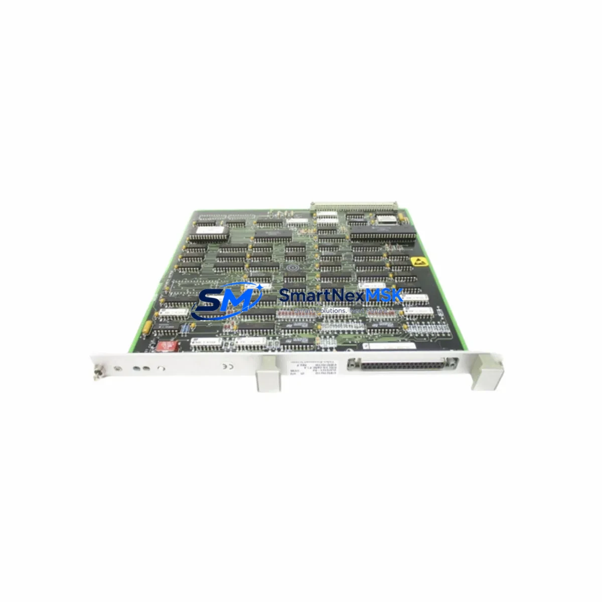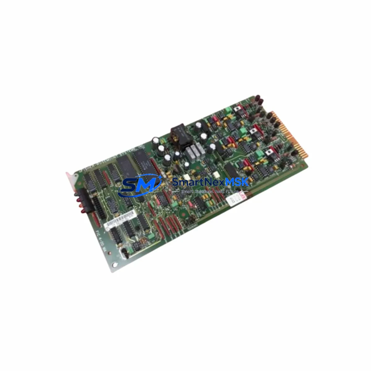
Fisher Controls 01984-2518-0002 Spare for Emerson DCS Automation
The Fisher Controls 01984-2518-0002 is an original analog I/O module engineered for continuous-duty service within Emerson DCS control architectures. For maintenance engineers managing aging distributed control systems, unplanned downtime caused by a failed analog I/O module can cascade across an entire process loop — halting production, triggering safety shutdowns, and compressing maintenance windows. Stocking a verified original spare of the 01984-2518-0002 is a proven strategy to compress mean-time-to-repair (MTTR) and restore normal operation within a single shift.
This module is sourced directly from authorized supply channels, 100% function-tested prior to shipment, and backed by a 12-month warranty. Each unit ships with full inspection documentation, making it suitable for regulated process industries including oil & gas, chemical, power generation, and pulp & paper.
Spare Maintenance Table
| SKU / Part Number | 01984-2518-0002 |
| Brand | Fisher Controls (Emerson) |
| Product Type | Analog I/O Module |
| Series / Platform | Emerson DCS / Fisher Controls Series |
| Signal Type | Analog Input / Output (4–20 mA, inferred) |
| Compatibility | Emerson DCS backplane; Fisher Controls analog I/O racks |
| Installation | Direct module slot replacement; no re-wiring required for like-for-like swap |
| Operating Environment | Industrial control cabinet; standard DCS environmental ratings |
| Origin | USA (OEM) |
| Condition | Original / New |
| Pre-shipment Testing | 100% function-tested |
| Warranty | 12 Months |
| Maintenance Recommendation | Inspect signal wiring, terminal blocks, and adjacent I/O modules during replacement; verify loop calibration post-installation |
Maintenance Planning for Continuous Operation
When a maintenance or procurement engineer schedules replacement of the 01984-2518-0002 analog I/O module, a disciplined site inspection of the surrounding control cabinet is essential to prevent repeat failures and ensure loop integrity. The following components should be evaluated concurrently:
- DCS Power Supply Module — Verify output voltage stability; a degraded power supply is a leading cause of premature I/O module failure. Emerson DCS power supply modules in the same rack should be load-tested during the maintenance window.
- Analog Signal Cables and Shielded Wiring — Inspect 4–20 mA signal cables for insulation damage, moisture ingress, and shield continuity. Degraded cabling introduces noise that can mask module faults.
- Terminal Blocks and Field Wiring Connectors — Check screw torque, corrosion, and contact integrity on all terminal blocks connected to the I/O module. Loose terminations are a common root cause of intermittent analog signal errors.
- Adjacent Analog I/O Modules — Modules in neighboring slots sharing the same backplane bus should be inspected for error LEDs, thermal discoloration, or communication faults. A failing neighbor module can corrupt shared bus signals.
- DCS Backplane / Carrier Card — Inspect the backplane connector for bent pins, oxidation, or mechanical damage before seating the replacement 01984-2518-0002. A damaged backplane will cause the new module to fail immediately.
- Signal Isolators and Barriers — If the analog loop passes through Zener barriers or galvanic isolators (common in hazardous-area installations), verify isolator output accuracy and replace any units showing drift beyond ±0.1% of span.
- Relay Output Modules — Where the analog I/O module drives relay-based control outputs, inspect relay output modules for contact wear, coil resistance, and response time. Relay modules in the same control loop should be part of the planned maintenance checklist.
- Communication Modules (HART / FOUNDATION Fieldbus) — If the process loop uses HART-enabled field devices, verify that the DCS communication module supporting HART pass-through is functioning correctly. A faulty communication module can prevent loop diagnostics from reaching the DCS historian.
- HMI Display and Operator Interface — After module replacement, confirm that the HMI correctly reflects restored analog values. Stale or frozen HMI readings may indicate a configuration or communication issue unrelated to the I/O module itself.
- Fuses and Circuit Protection — Replace any blown or degraded fuses in the I/O module’s field power circuit. Use OEM-specified fuse ratings to maintain protection coordination.
Maintaining a minimum of one spare 01984-2518-0002 module in the site spare parts inventory — alongside matched power supply and communication modules — is recommended for any facility operating Emerson DCS systems in continuous or safety-critical processes.
Site Replacement Workflow
Replacing the Fisher Controls 01984-2518-0002 follows a structured hot-swap or cold-swap procedure depending on the DCS platform configuration:
- Pre-replacement verification: Confirm the replacement module SKU matches the installed unit exactly. Cross-reference the 01984-2518-0002 part number against the DCS hardware configuration database and the physical label on the installed module.
- Loop isolation: Place affected control loops in manual mode at the DCS operator station. Notify process operators before isolating any analog input or output signal.
- Module extraction: Follow the OEM extraction procedure — typically releasing the module locking lever and sliding the module from the backplane slot. Avoid applying lateral force to the backplane connector.
- Backplane inspection: Before inserting the replacement, visually inspect the backplane slot for debris, oxidation, or pin damage.
- Module insertion and seating: Insert the 01984-2518-0002 replacement module firmly until the locking lever engages. Confirm the module status LED transitions to normal operating state.
- Loop restoration and calibration check: Return control loops to automatic mode. Verify analog signal values at the DCS historian and HMI against field instrument readings. Perform loop calibration if signal offset is detected.
- Documentation: Record the replacement in the site maintenance management system (CMMS), including the removed module serial number, replacement module serial number, and post-replacement loop verification results.
This workflow minimizes process disruption, maintains system compatibility, and creates an auditable maintenance record — critical for ISO 55001 asset management compliance and insurance documentation.
Spare Parts Support FAQ
Q1: What is the shelf life of the 01984-2518-0002 module in spare parts storage?
When stored in a dry, temperature-controlled environment (15–35°C, <70% RH, non-condensing) and in original anti-static packaging, analog I/O modules of this type typically maintain full functional integrity for 5–10 years. We recommend annual visual inspection of stored spares and functional testing every 3 years to confirm readiness.
Q2: How do I verify compatibility before installation?
Match the full part number — 01984-2518-0002 — against the DCS hardware configuration report and the physical label on the installed module. Confirm the backplane slot type, signal range (4–20 mA), and firmware revision requirements in the DCS system documentation. Our technical team can assist with compatibility verification prior to shipment upon request.
Q3: What pre-shipment testing is performed on each unit?
Every 01984-2518-0002 module is 100% function-tested before dispatch. Testing covers analog signal accuracy, backplane communication integrity, and power consumption within OEM specifications. A test report is available upon request for quality-critical procurement.
Q4: What does the 12-month warranty cover?
The 12-month warranty covers manufacturing defects and functional failures under normal operating conditions. It does not cover damage resulting from incorrect installation, overvoltage events, or environmental exposure beyond rated limits. Warranty claims are processed with full replacement or repair at no additional cost. Contact our technical support team to initiate a warranty claim.
© 2026 SMARTNEXMSK. All rights reserved.
Original Source: https://smartnexmsk.com
Contact: sales@smartnexmsk.com | +86 18259474341