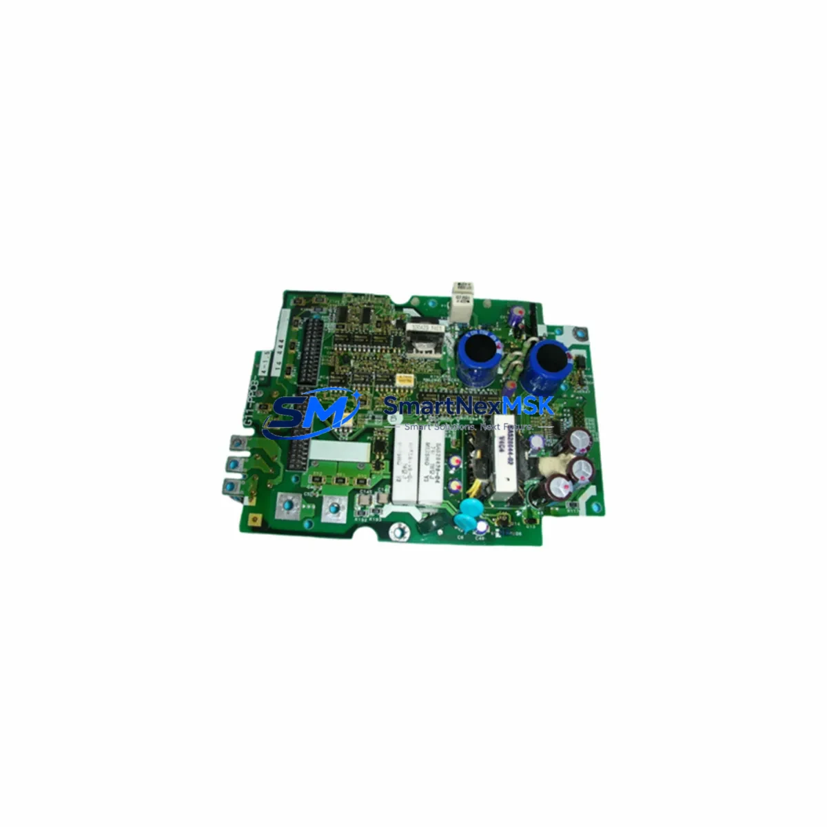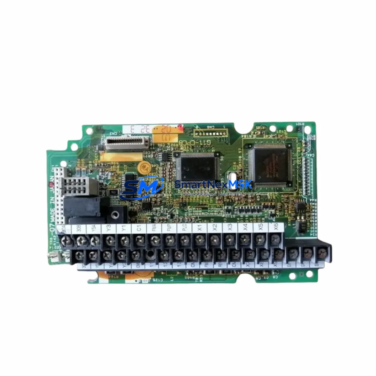
FUJI G11-CPCB SA529591-08 Maintenance-Ready Spare for Frenic G11 Automation
The FUJI G11-CPCB SA529591-08 is the original CPU control board designed for the Frenic G11 series variable frequency drive (VFD). As the central processing unit of the G11 drive, this board governs all core functions: speed reference processing, V/f and vector control algorithms, fault detection, keypad communication, and I/O signal management. When this board fails, the entire drive becomes inoperable — making rapid, verified replacement the only path to restoring production continuity.
For maintenance engineers managing aging Frenic G11 installations, sourcing an original SA529591-08 board — rather than an unverified substitute — is critical. Counterfeit or incompatible control boards can introduce parameter instability, false fault trips, or permanent drive damage. SMARTNEXMSK supplies only original FUJI boards, each tested before shipment and backed by a 12-month warranty.
Spare Maintenance Table
| Parameter | Specification / Detail |
|---|---|
| Part Number | G11-CPCB SA529591-08 |
| Full Description | CPU Control PCB for Frenic G11 VFD Series |
| Brand | FUJI Electric |
| Compatible Series | Frenic G11 (FRN□□□G11□-□) |
| Board Function | Main control CPU: speed reference, V/f & vector control, fault logic, I/O management |
| Communication Interface | RS-485 / Keypad port (RJ45); optional RS-232C adapter |
| I/O Terminals Supported | Multi-function analog inputs (0–10V / 4–20mA), digital inputs (FWD/REV/X1–X9), relay outputs (Y1–Y4) |
| Operating Temperature | -10°C to +50°C (drive enclosure ambient) |
| Origin | Japan |
| Condition | Original New / Tested Surplus |
| Pre-shipment Test | Power-on functional test performed on every unit |
| Warranty | 12 Months from date of shipment |
| Packaging | Anti-static bag + foam-lined carton |
| Lead Time | In-stock: ships within 2 business days |
| Application Environment | Industrial automation, pump/fan/compressor/conveyor VFD control panels |
| Maintenance Recommendation | Replace when drive displays CPU fault, communication loss, or unresponsive keypad after power cycle |
Maintenance Planning for Continuous Operation
A Frenic G11 VFD does not operate in isolation. The SA529591-08 control board interfaces with multiple subsystems inside the drive cabinet, and a thorough maintenance inspection should address each of them when replacing this board.
Begin with the power supply section: the G11’s internal SMPS board (e.g., SA529590 power supply PCB) provides regulated DC rails to the control board. A degraded SMPS can cause intermittent resets or corrupt parameter memory even after a control board swap — always verify SMPS output voltages before closing the cabinet. Similarly, inspect the gate driver board and IGBT module for signs of thermal stress or carbon tracking; a shorted IGBT can destroy a new control board within seconds of power-up.
On the I/O side, check all multi-function digital input terminals (FWD, REV, X1–X9) for correct 24VDC signal levels. Faulty signal isolators or broken shielded cables between the PLC output card and the VFD terminal block are a common source of nuisance trips that are often misdiagnosed as control board failures. If the plant uses a Fuji MICREX-SX or MICREX-F PLC to command the drive via RS-485, verify the communication cable integrity and termination resistors before replacing the board.
The analog input circuit (frequency reference via 0–10V or 4–20mA from a DCS analog output card) should be checked with a calibrated meter. A floating or noisy reference signal will cause speed instability that persists after board replacement. Inline signal isolators (such as DIN-rail mounted 4–20mA loop isolators) are recommended for long cable runs in electrically noisy environments.
For relay output circuits, inspect the output relay contacts (Y1–Y4) and downstream control relays or contactors for contact wear. The G11 control board drives these relays directly; a welded or high-resistance contact can back-feed voltage into the board’s output stage. Also verify the braking resistor and braking chopper circuit if the application involves regenerative loads — an open braking resistor causes DC bus overvoltage faults that are logged as control board errors.
Finally, review the keypad / operator panel (TP-G1 or compatible) and its RJ45 cable. A damaged keypad cable can prevent parameter upload after board replacement, stalling commissioning. Keeping a spare keypad and a tested RS-485 communication cable in the maintenance kit alongside the SA529591-08 board significantly reduces mean time to repair (MTTR).
Site Replacement Workflow
Step 1 — Document current parameters. Before powering down, upload all drive parameters to the keypad or a PC tool (FRENIC Loader software). The SA529591-08 board ships without pre-loaded parameters; restoring the original configuration is mandatory for correct operation.
Step 2 — Safe isolation. Isolate the drive from the AC supply and wait a minimum of 10 minutes for the DC bus capacitors to discharge below 25VDC. Verify with a calibrated meter before touching internal components.
Step 3 — Board removal. Disconnect all ribbon cables and terminal connectors from the existing control board in sequence. Photograph connector positions before removal. Ground yourself with an ESD wrist strap — electrostatic discharge is the leading cause of latent control board damage in field replacements.
Step 4 — Install SA529591-08. Seat the new board firmly, reconnect all cables in reverse order, and verify no connectors are partially seated. A partially connected ribbon cable is a common cause of post-replacement faults.
Step 5 — Parameter restore and commissioning. Power up the drive with the motor disconnected. Restore parameters from the saved file. Verify all I/O signals, analog references, and communication links before connecting the motor load. Run a no-load test at low speed before returning to full production.
This workflow is compatible with all Frenic G11 frame sizes and eliminates the most common commissioning errors that extend downtime beyond the board replacement itself.
Spare Parts Support FAQ
Q1: Is the G11-CPCB SA529591-08 compatible with all Frenic G11 frame sizes?
The SA529591-08 is the standard control CPU board used across the Frenic G11 series. Compatibility should be confirmed against the drive’s nameplate model number (FRN□□□G11□-□) and the existing board’s part number label. SMARTNEXMSK’s technical team can assist with cross-referencing before order confirmation.
Q2: How is each board tested before shipment?
Every SA529591-08 unit undergoes a power-on functional test verifying control power rails, communication port response, and I/O logic prior to packaging. Units that fail any test stage are quarantined and not shipped. A test report is available upon request for critical applications.
Q3: What does the 12-month warranty cover?
The warranty covers manufacturing defects and functional failures under normal operating conditions for 12 months from the shipment date. It does not cover damage caused by incorrect installation, overvoltage events, or ESD mishandling. SMARTNEXMSK provides replacement or full refund for confirmed warranty claims.
Q4: Can you support long-term or blanket purchase orders for ongoing maintenance programs?
Yes. SMARTNEXMSK maintains dedicated stock of high-demand Frenic G11 spare parts to support planned maintenance schedules and emergency call-out programs. Long-term supply agreements with reserved inventory allocation are available for industrial customers managing multiple G11 installations.
© 2026 SMARTNEXMSK. All rights reserved.
Original Source: https://smartnexmsk.com
Contact: sales@smartnexmsk.com | +86 18259474341