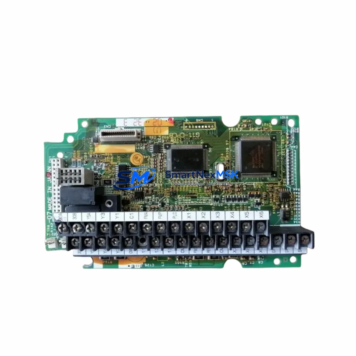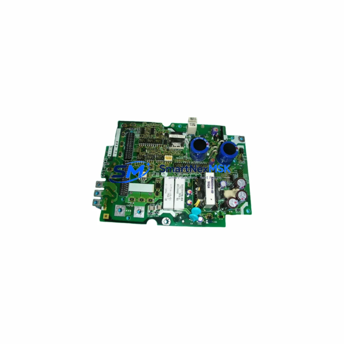
FUJI SA528530-06 Retrofit-Ready Power PCB for G11 Control Systems: Compatible Upgrade for Legacy FRENIC G11 Drives
The FUJI SA528530-06 is a retrofit-ready power printed circuit board (PPCB) engineered for the FRENIC G11 series variable frequency drive platform. Designed as a direct replacement for aging or failed power PCBs in G11-series drives rated at 4-pole, 1.5 kW configurations, this board enables industrial facilities to restore full drive functionality without replacing the entire inverter unit. With verified compatibility across the FRENIC G11 control architecture, the SA528530-06 is the preferred choice for maintenance engineers managing legacy automation systems, aging production lines, and control cabinet upgrades where minimizing capital expenditure is critical.
Whether your facility is executing a planned retrofit of an older FRENIC G11 drive or responding to an unplanned board failure, the SA528530-06 provides a reliable, cost-effective path to system recovery. The board is fully tested prior to shipment and backed by a 12-month warranty, giving procurement and maintenance teams confidence in both quality and supply continuity.
Upgrade Compatibility Table
| Parameter | Details |
|---|---|
| SKU / Part Number | SA528530-06 |
| Compatible Drive Series | FUJI FRENIC G11 (4-pole, 1.5 kW) |
| Board Function | Power PCB (PPCB) — DC bus regulation, gate drive signal, power supply to control board |
| Interface / Connector | Direct plug-in to G11 main chassis backplane; standard ribbon and terminal block connectors |
| Installation Requirement | Requires discharge of DC bus capacitors before removal; torque spec per G11 service manual |
| Communication Compatibility | Compatible with RS-485 / Modbus RTU option cards installed in the G11 option slot |
| Replacement Recommendation | Direct drop-in replacement; no firmware re-flash required for standard G11 configurations |
| Commissioning Notes | Verify parameter group F01–F03 (frequency reference, run command source) after board swap; re-run auto-tuning if motor parameters were stored on original board |
| Warranty | 12 months from date of shipment |
Retrofit Planning for Existing Automation Systems
Replacing the power PCB in a FRENIC G11 drive is rarely an isolated task — it is typically part of a broader control system maintenance or modernization effort. Before beginning the swap, engineers should audit the full drive assembly. The FRENIC G11 control board (the logic PCB that interfaces with the PPCB) should be inspected for corrosion or thermal damage, as a failed power board can sometimes stress the control board’s power rails. If the control board shows signs of degradation, replacing both boards simultaneously reduces the risk of repeat downtime.
In multi-drive control cabinets, the SA528530-06 retrofit is often performed alongside inspection of the FRENIC G11 gate driver board and the DC bus capacitor bank. Capacitor aging is a primary cause of power PCB stress in drives that have been in service for more than seven years. Replacing the capacitor bank at the same time as the PPCB is a best practice that extends the service interval significantly.
For facilities running the FRENIC G11 alongside other FUJI inverter platforms — such as the FRENIC-Ace, FRENIC-Multi, or FRENIC-MEGA series — it is important to note that power PCBs are not cross-compatible between series. Each platform uses a dedicated board architecture. However, the FUJI TP-E1-1 programming keypad and FUJI OPC-G11S-PDP PROFIBUS-DP option card are shared accessories that may already be present in your facility’s spare parts inventory.
When the G11 drive is integrated into a PLC-based control system — for example, a FUJI MICREX-SX series PLC or a third-party controller communicating via the OPC-G11S-RS option card (RS-485 / Modbus RTU) — the retrofit plan must include verification of the communication link after board replacement. The Modbus device address, baud rate, and parity settings stored in parameter group H30–H39 should be documented before the board is removed and re-entered after installation. If the facility uses an HMI panel (such as a FUJI V9 series or equivalent) with drive status screens mapped to G11 register addresses, those screens should be tested for correct data display after the retrofit is complete.
For I/O-intensive applications, confirm that the FRENIC G11 terminal board — which carries analog input (AI1, AI2), digital input (X1–X5), and relay output (Y1, 30A/30B/30C) wiring — is undamaged and that all terminal screws are re-torqued to specification after the power PCB is seated. Loose terminal connections are a leading cause of nuisance faults following board-level maintenance. If the application uses a FUJI OPC-G11S-PG pulse generator option card for encoder feedback in closed-loop vector control, verify encoder signal integrity with an oscilloscope before returning the drive to service.
Downtime Control During System Migration
Unplanned drive failures in continuous-process industries — food processing, water treatment, HVAC, and material handling — can result in significant production losses. The SA528530-06 is stocked for immediate dispatch, enabling same-day or next-day shipment to minimize the gap between failure and restoration.
To further reduce downtime, maintenance teams should follow a structured swap protocol: (1) isolate and lock out the drive per LOTO procedures; (2) measure and confirm DC bus voltage has discharged below 30 V before touching internal components; (3) photograph all wiring and connector positions before disconnection; (4) seat the SA528530-06 and reconnect all harnesses in reverse order; (5) power up in local keypad mode (not remote run command) and verify output voltage balance across U, V, W phases before reconnecting the motor load.
For facilities with a hot-standby or redundant drive strategy, the SA528530-06 can be pre-installed in a spare G11 chassis and kept on the shelf, ready for a chassis-swap rather than a board-level repair. This approach reduces mean time to repair (MTTR) to under 30 minutes in most installations. All original program parameters — including acceleration/deceleration ramps, torque boost settings, and PID control constants — should be backed up using the FUJI TP-E1-1 keypad copy function or a PC-based parameter backup tool before any maintenance activity begins, ensuring that program logic is preserved regardless of board replacement outcome.
Retrofit Support FAQ
Q1: Is the SA528530-06 a direct replacement for the original FUJI G11-PPCB-4-1.5 power board?
Yes. The SA528530-06 is the OEM part number for the power PCB used in FUJI FRENIC G11 drives at the 4-pole, 1.5 kW rating. It is a direct, plug-compatible replacement that requires no hardware modification to the drive chassis. Verify the drive’s nameplate rating and existing board part number before ordering to confirm compatibility.
Q2: What commissioning steps are required after installing the SA528530-06?
After installation, power the drive in local keypad mode and confirm that the keypad displays normally without fault codes. Re-enter any motor parameters (rated voltage, current, frequency, speed) if they were not backed up prior to the board failure. Run the drive at low speed (5–10 Hz) unloaded to verify output phase balance, then perform a full-load test before returning to automatic operation. If the drive uses auto-tuning (parameter H04), re-run the tuning sequence with the motor connected.
Q3: Will the SA528530-06 work with my existing RS-485 / Modbus RTU communication setup?
Yes. The SA528530-06 is compatible with the FUJI OPC-G11S-RS option card for RS-485 / Modbus RTU communication. After board replacement, re-enter the Modbus station address (H30), baud rate (H31), and data format (H32) parameters. Test communication from the PLC or SCADA system before enabling remote run commands.
Q4: What does the 12-month warranty cover, and how is it claimed?
The 12-month warranty covers manufacturing defects and functional failures under normal operating conditions. It does not cover damage caused by incorrect installation, overvoltage events, or environmental contamination. To claim warranty service, contact our sales team with the order number and a description of the fault. All boards are tested prior to shipment; a pre-shipment test report is available upon request.
© 2026 SMARTNEXMSK. All rights reserved.
Original Source: https://smartnexmsk.com
Contact: sales@smartnexmsk.com | +86 18259474341