GE 44A751862-G01 Retrofit-Ready DCS CPU for Series Six Control Systems
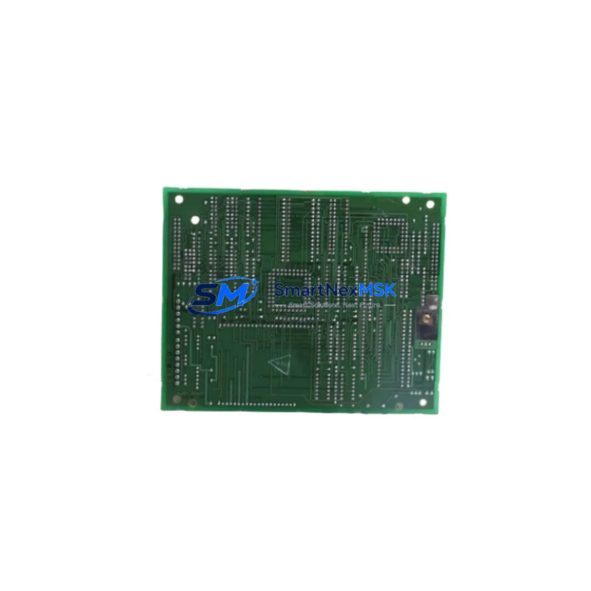
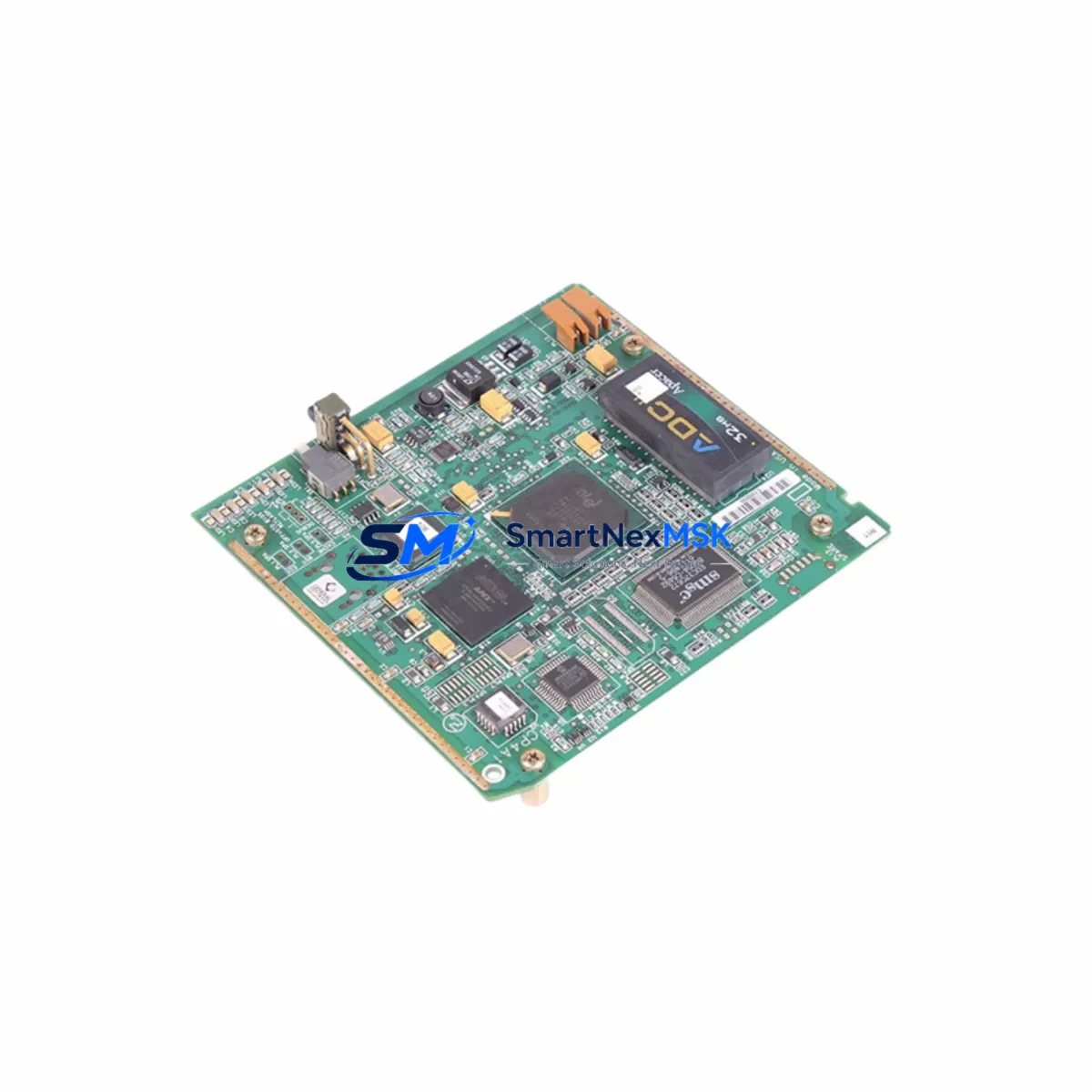
The GE 44A751862-G01 is a CPU processor board originally designed for the General Electric Series Six distributed control system (DCS) platform — one of the most widely deployed process-automation architectures in power generation, petrochemical, and heavy manufacturing facilities. As the Series Six platform has reached end-of-life and OEM support has been discontinued, the demand for verified replacement units, tested retrofit boards, and compatible upgrade paths has grown significantly across global industrial sites.
SMARTNEXMSK maintains a dedicated inventory of the 44A751862-G01 CPU board, sourced from decommissioned systems, tested against original GE factory specifications, and backed by a 12-month warranty. Each unit undergoes functional verification prior to shipment, including power-on self-test, backplane communication checks, and I/O bus integrity validation. This ensures that your replacement board arrives ready for installation with minimal commissioning time on site.
Upgrade Compatibility Table
| Parameter | Details |
|---|---|
| SKU / Part Number | 44A751862-G01 |
| Brand / OEM | General Electric (GE) |
| Platform | Series Six DCS |
| Module Function | Central Processing Unit (CPU) Board |
| Backplane Interface | Series Six proprietary parallel bus |
| Communication Compatibility | GE GENET, Modbus RTU (via gateway), proprietary serial |
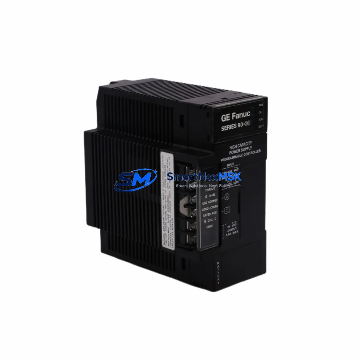
| Power Supply Requirement | +5 VDC / +12 VDC from Series Six rack PSU (e.g. 44A726158-G01 or equivalent) |
| Rack / Chassis Fit | Series Six standard 19″ rack enclosure, compatible with 7-slot and 14-slot backplanes |
| Replacement Recommendation | Direct drop-in for failed or degraded 44A751862-G01 units; verify firmware revision before swap |
| Commissioning Notes | Module address DIP switches must match original configuration; re-download application logic after installation |
| Warranty | 12 Months — covers functional failure under normal operating conditions |
| Condition | Tested, refurbished; original GE factory spec |
| Lead Time | In stock — ships within 2 business days |
Retrofit Planning for Existing Automation Systems
Replacing the 44A751862-G01 CPU board in an active Series Six DCS installation requires careful pre-planning to protect existing program logic, field wiring, and operator interface continuity. Before initiating the swap, engineers should document the current module address settings using the DIP switch map on the original board and photograph all terminal block wiring on associated Series Six I/O modules — including analog input boards, digital output boards, and thermocouple input cards that share the same rack.
The Series Six rack power supply — typically a 44A726158-G01 or similar dual-output PSU — should be load-tested prior to installing the replacement CPU. An undersized or aging power supply is a common root cause of repeated CPU board failures in legacy DCS cabinets, and replacing the CPU without addressing power quality will result in premature failure of the new board. Verify that the +5 VDC rail holds within ±5% under full rack load before proceeding.
For sites migrating from Series Six to a modern platform such as the GE Mark VIe or a third-party DCS, the 44A751862-G01 can serve as a bridge solution — maintaining production continuity while the new control system is engineered, programmed, and staged in parallel. During this transition period, communication gateways such as Modbus-to-Ethernet protocol converters are frequently used to link the legacy Series Six network to SCADA systems or historian platforms, allowing operators to maintain visibility across both old and new control layers.
When the replacement CPU is installed, the application program must be re-downloaded from the engineering workstation using the original GE Series Six programming software. Confirm that the Series Six programming cable and workstation software version are compatible with the firmware revision on the replacement board. If the firmware revision differs from the original, a firmware update may be required before the program download can proceed. HMI screens connected via the GENET network should be verified for tag mapping integrity after the CPU swap, as address offsets can shift if module slot assignments have changed.
For I/O expansion during the retrofit, sites commonly add Series Six analog output modules or digital input expansion cards to the existing rack to support new field instruments installed as part of the modernization project. Ensure that the total I/O count does not exceed the CPU’s scan capacity, and that the backplane slot assignments are updated in the application program accordingly. If the existing 7-slot rack is at capacity, a Series Six 14-slot expansion rack with a remote I/O adapter may be required.
Downtime Control During System Migration
Minimizing unplanned downtime is the primary concern for any Series Six CPU replacement. The recommended approach is a hot-standby swap procedure: with the rack powered down, the replacement 44A751862-G01 is installed, DIP switches are configured to match the original module address, and the rack is powered up before the application program is downloaded. Total controlled downtime for a straightforward CPU swap is typically 30–90 minutes, depending on program size and communication re-establishment time.
To protect the original program logic, always maintain a current backup of the Series Six application on a dedicated engineering workstation before initiating any hardware change. If the original program file is unavailable — a common situation with legacy systems that have changed hands — SMARTNEXMSK can advise on program recovery options using the existing CPU’s memory, provided the board is still partially functional.
For critical continuous-process applications where even a brief shutdown is unacceptable, a parallel migration strategy is recommended: the replacement CPU is staged and tested in a bench environment using a spare rack and representative I/O simulation before the live system is touched. This approach allows full functional verification of the replacement board, including communication link establishment, program execution, and HMI tag validation, without impacting production. Once bench testing is complete, the live cutover can be executed during a planned maintenance window with high confidence and a well-rehearsed procedure.
Field commissioning after the CPU swap should include a full I/O loop check on all critical control loops, verification of interlock logic, and a timed scan-cycle test to confirm that the CPU is executing the application program within the original cycle time specification. Any deviation in scan time may indicate a hardware incompatibility or a program configuration issue that should be resolved before returning the system to automatic control.
Retrofit Support FAQ
Q1: Is the 44A751862-G01 a direct replacement for my existing Series Six CPU board?
Yes. The 44A751862-G01 is a direct form-fit-function replacement for the original GE Series Six CPU board of the same part number. Before installation, verify that the firmware revision on the replacement unit matches or is compatible with your existing application program version. DIP switch settings for module address must be replicated from the original board.
Q2: What wiring changes are required when replacing the CPU board?
The 44A751862-G01 CPU board connects to the Series Six backplane via the rack edge connector — no field wiring is directly terminated on the CPU board itself. Field wiring is terminated on the associated I/O modules in the same or expansion rack. No wiring changes are required for a like-for-like CPU replacement, provided the rack slot assignment remains unchanged.
Q3: How do I verify compatibility with my existing Series Six communication network?
The Series Six GENET communication network is managed at the CPU level. After installing the replacement 44A751862-G01, re-establish the GENET node address using the DIP switch configuration documented in the GE Series Six hardware manual. Verify communication with all peer nodes — including remote I/O adapters, operator stations, and any Modbus gateway devices — before returning the system to service.
Q4: What does the 12-month warranty cover?
The 12-month warranty covers functional failure of the 44A751862-G01 CPU board under normal operating conditions, including backplane communication faults, processor failure, and memory errors. The warranty does not cover damage resulting from incorrect installation, overvoltage, electrostatic discharge, or physical impact. In the event of a warranty claim, SMARTNEXMSK will provide a tested replacement unit and coordinate return logistics at no additional cost.
© 2026 SMARTNEXMSK. All rights reserved.
Original Source: https://smartnexmsk.com
Contact: sales@smartnexmsk.com | +86 18259474341