GE FEG-S032-J001 Retrofit-Ready Output Module for L54E Series Control Systems
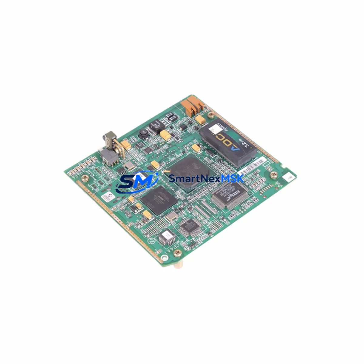
The GE FEG-S032-J001 is a discrete output module engineered for seamless integration into GE Series 90 and L54E-platform control architectures. As legacy L54E2900WH-based systems approach end-of-support milestones, plant engineers and system integrators increasingly rely on the FEG-S032-J001 as a verified, drop-in replacement that preserves existing rack geometry, terminal wiring, and ladder logic without requiring a full controller migration. SMARTNEXMSK maintains ready stock of this module with full functional testing and a 12-month warranty on every unit shipped.
Whether you are managing a scheduled control cabinet upgrade, responding to an unplanned module failure, or executing a phased I/O expansion across a multi-rack installation, the FEG-S032-J001 delivers the output density and signal integrity required to maintain production continuity. Its compatibility with the GE IC693 backplane family means it can be seated alongside existing IC693MDL940, IC693MDL645, and IC693MDL741 I/O modules without reconfiguring rack addressing or power budgets.
Upgrade Compatibility Table
| Parameter | FEG-S032-J001 (Replacement) | Legacy L54E2900WH Module |
|---|---|---|
| Backplane Interface | GE IC693 Series 90 compatible | IC693 / L54E native slot |
| Output Type | Discrete relay / solid-state output | Discrete relay output |
| Terminal Wiring | Standard 20-pin removable terminal block | 20-pin fixed terminal block |
| Communication Protocol | Backplane bus (Series 90 native) | Backplane bus (Series 90 native) |
| Module Address Config | Auto-detected via rack slot position | Slot-based addressing |
| Power Consumption | Verify against IC693PWR321 / IC693PWR330 budget | Refer to original panel BOM |
| HMI Screen Compatibility | No HMI tag remapping required | Existing tags retained |
| Replacement Recommendation | Direct slot-for-slot swap; no program changes | — |
| Commissioning Focus | Force-test each output point; verify field device response | — |
| Warranty | 12-Month SMARTNEXMSK Warranty | OEM warranty expired |
Retrofit Planning for Existing Automation Systems
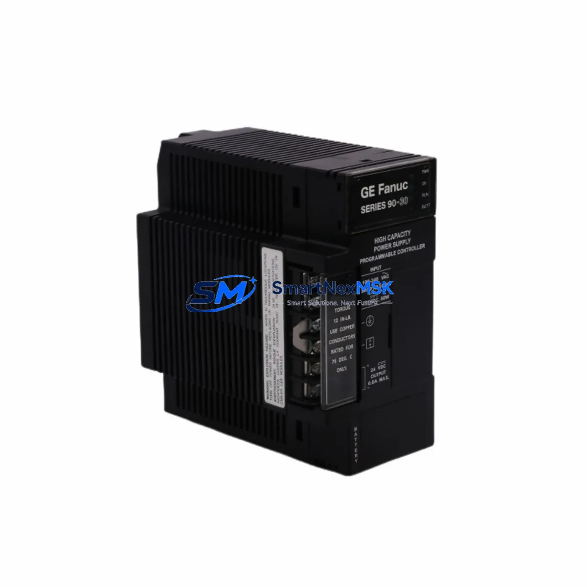
A successful retrofit of the FEG-S032-J001 into an operating L54E2900WH system begins well before the module arrives on site. The first step is a power audit of the existing rack. The IC693PWR321 or IC693PWR330 power supply module must have sufficient headroom to support the replacement output module alongside any co-installed analog input modules such as the IC693ALG221 or IC693ALG222. If the power budget is marginal, an additional power supply or a rack expansion using the IC693CHS391 five-slot expansion chassis should be evaluated before the cutover window.
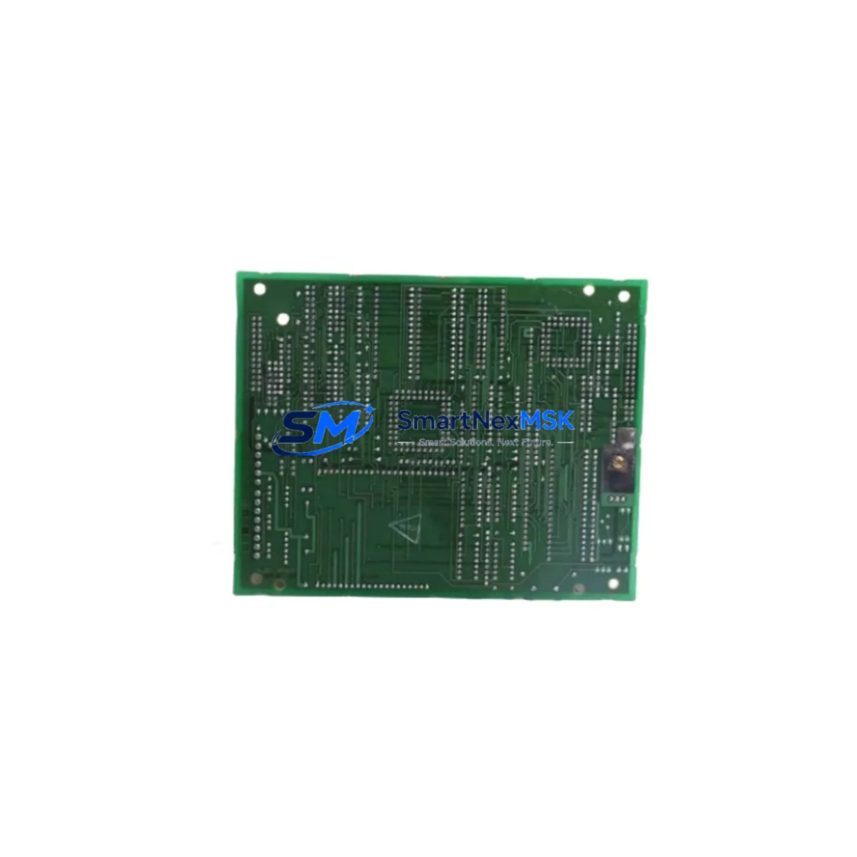
Terminal wiring is the next critical checkpoint. The FEG-S032-J001 uses a removable terminal block, which simplifies field replacement compared to the fixed-terminal legacy module. Technicians should photograph and document the existing field wiring before removal, then transfer conductors to the new terminal block off-line to minimize energized work time. Each output circuit should be verified against the original panel schematic, paying particular attention to common return wiring shared across output groups.
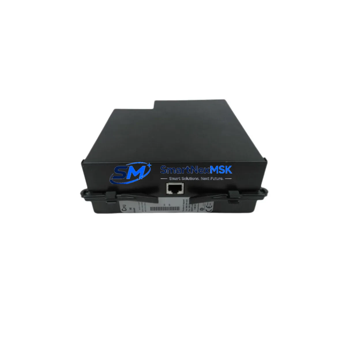
On the controller side, the IC693CPU374 or IC693CPU375 CPU module retains the existing ladder logic program in battery-backed RAM. Because the FEG-S032-J001 occupies the same rack slot and presents an identical I/O reference address to the CPU, no program download is required after the swap. Engineers should confirm this by reviewing the hardware configuration in Proficy Machine Edition before the outage, ensuring the slot definition matches the replacement module type. If the site uses an IC693CMM321 or IC693CMM311 communications module for Modbus or SRTP connectivity to a SCADA host, the communication link should be verified post-swap by monitoring live data tags from the control room.
For installations where the L54E2900WH rack also hosts an IC693MDL655 32-point DC input module or an IC693MDL940 relay output module in adjacent slots, the FEG-S032-J001 installation does not disturb those modules’ configurations. The backplane bus arbitration is handled transparently by the CPU, and no slot-level re-addressing is needed. If the site is also migrating from a legacy GE Fanuc Series Six or Series Five controller to the Series 90 platform, the FEG-S032-J001 is compatible with the target architecture and can be pre-staged in the new rack before the full controller cutover.
Downtime Control During System Migration
Minimizing unplanned downtime is the primary operational concern when replacing output modules in a live production environment. SMARTNEXMSK recommends a structured hot-swap protocol: schedule the replacement during a planned maintenance window, pre-configure the FEG-S032-J001 terminal block off-line, and stage the module at the panel before initiating the CPU stop sequence. The entire physical swap — removing the legacy module, seating the FEG-S032-J001, and reconnecting the terminal block — typically takes under ten minutes for a trained technician.
Before issuing the CPU RUN command, perform a forced-output test on each point using the Proficy Machine Edition online monitor or the handheld programmer to confirm field device response. This step protects the original ladder logic from executing against unverified field wiring. Once all output points are confirmed, release the CPU to RUN mode and monitor the first production cycle from the HMI. The existing HMI screens, built on iFIX, CIMPLICITY, or a third-party SCADA, require no modification because the I/O reference addresses are unchanged.
For multi-rack systems where the L54E2900WH installation spans several IC693CHS392 or IC693CHS398 expansion racks connected via the IC693BEM331 bus expansion module, the replacement of a single output module in one rack does not affect the bus topology or the I/O scan cycle of modules in other racks. This isolation characteristic allows phased module replacement across a large installation without a full system shutdown, preserving field control continuity throughout the upgrade campaign.
Retrofit Support FAQ
Q1: Is the FEG-S032-J001 a direct replacement for the L54E2900WH output module without any program changes?
Yes. The FEG-S032-J001 occupies the same rack slot and presents the same I/O reference address to the IC693 CPU. No ladder logic modifications or hardware configuration downloads are required, provided the slot definition in Proficy Machine Edition already matches the module type. Verify the hardware configuration file before the outage to confirm compatibility.
Q2: What wiring checks are required before powering up the replacement module?
Confirm that all field conductors are correctly seated in the removable terminal block, that common return wiring is intact, and that no output circuit exceeds the module’s rated load current. Use a continuity tester on de-energized circuits before applying power. After power-up, perform a forced-output test on each point before releasing the CPU to RUN mode.
Q3: Does the FEG-S032-J001 support the same communication protocols as the legacy module?
The FEG-S032-J001 communicates via the Series 90 backplane bus and is fully compatible with SRTP, Modbus RTU (via IC693CMM311), and Modbus TCP (via IC693CMM321) communication modules installed in the same rack. No protocol reconfiguration is required at the SCADA or HMI level.
Q4: What does the 12-month warranty cover, and how is the module tested before shipment?
Every FEG-S032-J001 shipped by SMARTNEXMSK undergoes full functional testing including output point actuation, backplane communication verification, and load cycling before dispatch. The 12-month warranty covers manufacturing defects and functional failures under normal operating conditions. Units are shipped with a test report. Contact sales@smartnexmsk.com for warranty claims or pre-shipment inspection requests.
© 2026 SMARTNEXMSK. All rights reserved.
Original Source: https://smartnexmsk.com
Contact: sales@smartnexmsk.com | +86 18259474341