GE IC200MDL740 Maintenance-Ready Spare for VersaMax Automation
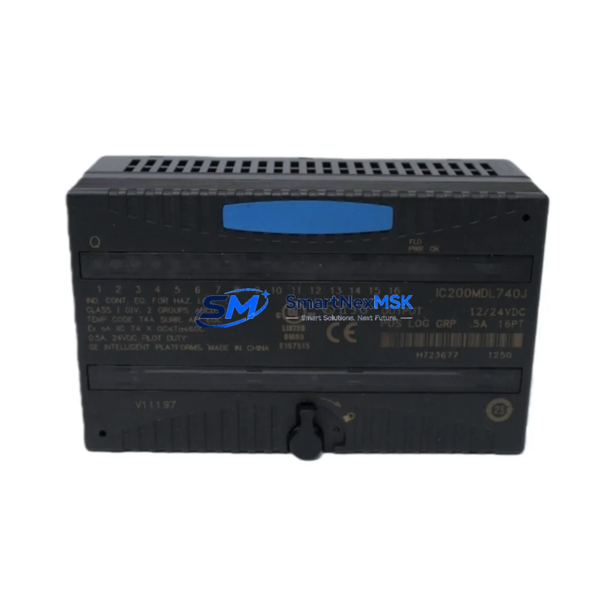
The GE IC200MDL740 is a 16-point, 120VAC discrete output module designed for the GE VersaMax PLC platform — one of the most widely deployed modular control architectures in North American and global industrial facilities. As a maintenance-ready original spare, the IC200MDL740 is engineered to deliver direct drop-in replacement capability, enabling maintenance and reliability engineers to restore control system operation with minimal downtime and zero re-engineering effort.
In industrial environments where unplanned downtime translates directly to production loss, having a verified original IC200MDL740 on the shelf is a critical element of any preventive maintenance strategy. Whether your facility operates continuous process lines, discrete manufacturing cells, or hybrid automation systems, this module supports fast fault isolation, rapid swap-out, and immediate return to normal operation — all without requiring firmware reconfiguration or I/O remapping when replacing a like-for-like unit.
Each IC200MDL740 unit shipped by SMARTNEXMSK is subject to pre-shipment functional testing, covering output channel integrity, backplane communication, and module identification. All units are covered by a 12-month warranty from the date of shipment, providing procurement and maintenance teams with long-term supply confidence for aging VersaMax installations.
Spare Maintenance Table
| Parameter | Specification |
|---|---|
| Model / SKU | IC200MDL740 |
| Brand / OEM | GE (General Electric / Emerson Automation Solutions) |
| Series | VersaMax Modular PLC |
| Module Type | Discrete Output Module |
| Output Points | 16 Points |
| Output Voltage | 120VAC |
| Output Type | Triac (Solid-State AC Output) |
| Load Current per Point | 0.5A max |
| Total Module Load | 4A max (all points ON) |
| Backplane Interface | VersaMax Local / Remote I/O Backplane |
| Compatible Carriers | IC200CHS002, IC200CHS005, IC200CHS022 |
| Compatible CPUs | IC200CPUE05, IC200CPUE05S, IC200CPU001, IC200CPU002 |
| Operating Temperature | 0°C to 60°C |
| Relative Humidity | 5% to 95% non-condensing |
| Mounting | DIN Rail / Panel via VersaMax Carrier |
| Origin | United States |
| Condition | Original / New Surplus / Tested |
| Warranty | 12 Months from Shipment Date |
| Pre-Shipment Test | Output channel integrity, backplane communication, module ID verification |
Maintenance Planning for Continuous Operation
When a maintenance or reliability engineer identifies a failed or degraded IC200MDL740 in a VersaMax rack, the replacement workflow should extend beyond the module itself. A thorough site inspection during the swap-out window significantly reduces the risk of repeat failures and unplanned outages.
Begin by inspecting the IC200PWR001 or IC200PWR002 power supply module feeding the VersaMax rack. AC output modules are sensitive to supply voltage fluctuations; a degraded power supply can cause premature output triac failure. Verify output voltage stability under load before reinstalling the replacement IC200MDL740.
Next, examine the IC200CHS002 or IC200CHS005 carrier/backplane for signs of oxidation, cracked connectors, or bent backplane pins. A damaged carrier can cause intermittent communication faults that mimic module failure and will damage a replacement module if not addressed.
Check all field wiring terminal blocks connected to the output module. Loose or corroded terminals on 120VAC output circuits are a common root cause of nuisance tripping and output channel burnout. Torque all terminals to specification and inspect for discoloration indicating prior overload events.
If the VersaMax system uses a IC200MDL640 or IC200MDL650 discrete input module in the same control loop, verify input signal integrity as part of the fault isolation process. A failed output module is sometimes the downstream symptom of an input signal anomaly or PLC logic fault.
For systems with IC200ALG320 or IC200ALG260 analog I/O modules in adjacent slots, confirm that the backplane communication bus is clean and that no ground loops have developed — particularly in mixed AC/DC I/O configurations where the IC200MDL740 operates alongside low-voltage analog circuits.
Review the IC200CPU001 or IC200CPUE05 CPU module diagnostic LEDs and fault table after module replacement. Clear any latched I/O faults and perform a controlled output test sequence before returning the system to automatic operation. If the CPU logs recurring I/O bus errors, inspect the IC200BEM002 bus expansion module or remote I/O drop cabling for signal integrity issues.
For facilities maintaining a spare parts inventory, it is recommended to stock at least one IC200MDL740 per VersaMax rack that uses 120VAC output circuits, alongside a matched IC200MDL730 (120VAC input module) for complete I/O redundancy coverage. Pairing these with a spare IC200PWR001 power supply and a set of IC200CHS carrier assemblies provides a self-contained recovery kit for the most common VersaMax field failures.
Site Replacement Workflow
Step 1 — Fault Confirmation: Use the VersaMax CPU fault table or GE Proficy Machine Edition diagnostic tools to confirm the IC200MDL740 as the fault source. Document the slot address and I/O map before removal.
Step 2 — Safe Isolation: De-energize the 120VAC field circuits connected to the module output terminals. Do not rely solely on PLC output disable — physically isolate the field power supply feeding the output load circuits.
Step 3 — Module Removal: Release the module locking tab on the VersaMax carrier and slide the IC200MDL740 straight out of the backplane slot. Avoid lateral force to protect the backplane connector.
Step 4 — Carrier Inspection: Inspect the vacated slot on the IC200CHS carrier for debris, moisture, or connector damage before inserting the replacement module.
Step 5 — Replacement Installation: Insert the new IC200MDL740 into the same slot position. The module is keyed to prevent incorrect installation. Engage the locking tab fully.
Step 6 — Power-Up and Verification: Re-energize the rack and observe the module status LED. A solid green LED indicates successful backplane recognition. Clear any CPU fault logs and perform a supervised output test on all 16 channels before returning to automatic control.
Step 7 — Documentation: Record the replacement date, module serial number, and test results in the site maintenance log. Update the spare parts inventory to trigger reorder of a replacement IC200MDL740 for the next maintenance cycle.
Spare Parts Support FAQ
Q1: Is the IC200MDL740 a direct replacement for all VersaMax 120VAC output applications?
The IC200MDL740 is the standard 16-point 120VAC triac output module for the VersaMax platform and is directly interchangeable with prior production runs of the same model number. It is compatible with all VersaMax local and remote I/O carriers (IC200CHS series) and all VersaMax-compatible CPUs. No firmware changes or I/O remapping are required for like-for-like replacement.
Q2: What does the 12-month warranty cover?
The 12-month warranty covers manufacturing defects, functional failures under normal operating conditions, and backplane communication faults attributable to the module itself. Warranty claims are supported by SMARTNEXMSK with advance replacement options for critical production environments. The warranty period begins from the confirmed shipment date.
Q3: How do you verify module condition before shipment?
Each IC200MDL740 unit undergoes pre-shipment testing that includes output channel continuity verification, backplane connector inspection, module identification confirmation, and functional power-up testing where applicable. Test records are available upon request for quality-critical procurement requirements.
Q4: Can you support long-term or blanket orders for VersaMax spare parts?
Yes. SMARTNEXMSK supports scheduled delivery agreements, blanket purchase orders, and multi-SKU VersaMax spare parts kits for facilities managing aging GE automation infrastructure. Contact our technical sales team to discuss inventory reservation, lead time commitments, and multi-line spare parts programs tailored to your maintenance schedule.
© 2026 SMARTNEXMSK. All rights reserved.
Original Source: https://smartnexmsk.com
Contact: sales@smartnexmsk.com | +86 18259474341