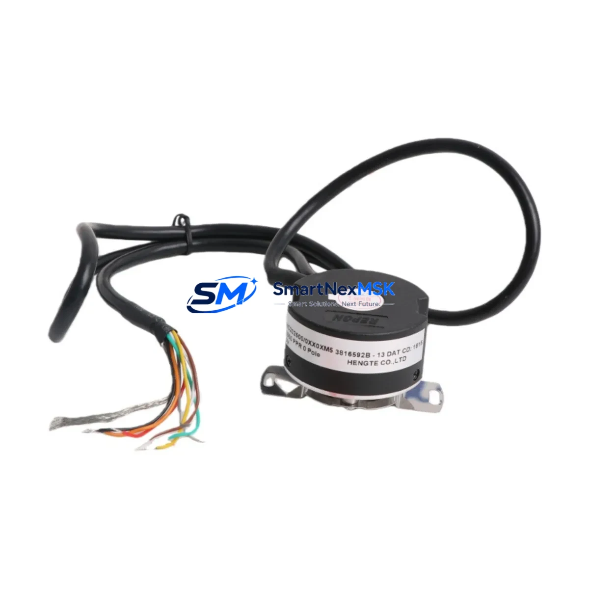
HENGSTLER AR62/1212EL.7XSGB-K0:6115 Retrofit-Ready Incremental Encoder for AR62 Control Systems
The HENGSTLER AR62/1212EL.7XSGB-K0:6115 is a high-resolution incremental rotary encoder engineered for seamless integration into legacy and modern industrial control architectures. With 1212 pulses per revolution (PPR), push-pull output, and a robust shaft design rated for continuous industrial duty, this encoder is the preferred retrofit solution for engineers tasked with upgrading aging motion-control and positioning systems without full line redesign.
Whether you are replacing a failed unit on a CNC axis, modernizing a legacy servo drive loop, or migrating a packaging line from an obsolete encoder platform, the AR62/1212EL.7XSGB-K0:6115 delivers the electrical and mechanical compatibility required to restore full system functionality with minimal downtime. Its 5–30 V DC supply range accommodates both older 24 V PLC I/O cards and newer 5 V differential input modules, eliminating the need for signal converters in most retrofit scenarios.
Upgrade Compatibility Table
| Parameter | AR62/1212EL.7XSGB-K0:6115 Specification | Retrofit Notes |
|---|---|---|
| Output Type | Push-Pull (HTL/TTL compatible) | Compatible with most SIEMENS S7-300/S7-400 high-speed counter modules (e.g., FM 350-1) and Mitsubishi QD62 counter units |
| Resolution | 1212 PPR | Verify PLC counter module max frequency; at 3000 RPM = ~60.6 kHz — within FM 350-1 and QD62 rated limits |
| Supply Voltage | 5–30 V DC | Direct replacement for 24 V HTL encoders; no signal converter required for standard PLC I/O |
| Shaft / Flange | 6 mm solid shaft, synchro flange | Confirm coupling bore and flange bolt pattern before installation; adapter plates available for Euro-flange variants |
| Connector | 7-pin connector (XSGB) | Re-pin or replace field cable if existing harness uses M12 or D-sub termination |
| Communication Compatibility | Incremental A/B/Z pulse (no fieldbus) | Interfaces directly with PROFIBUS DP encoder gateways or SSI converter modules for network-integrated systems |
| Replacement Suitability | Direct drop-in for AR62 series variants with matching PPR and connector | Cross-reference AR62/1000EL, AR62/2048EL variants if PPR differs; confirm with engineering before substitution |
| Commissioning Focus | Zero-pulse (Z) alignment, direction polarity | Re-home axis after installation; verify Z-pulse position in PLC homing routine |
| Warranty | 12-Month Warranty | Covers manufacturing defects; includes pre-shipment functional test report |
Retrofit Planning for Existing Automation Systems
Successful integration of the AR62/1212EL.7XSGB-K0:6115 into an existing control system begins well before the encoder arrives on site. Engineers should start by auditing the existing encoder wiring harness and terminal block layout inside the control cabinet. In many legacy installations, the encoder cable is routed through a HENGSTLER or third-party junction box before terminating at the PLC’s high-speed counter input card. If the system uses a SIEMENS FM 350-1 or FM 350-2 counter module, the A, B, and Z channel assignments must be verified against the existing hardware configuration in STEP 7 or TIA Portal before the new encoder is powered up.
For systems built around Mitsubishi MELSEC Q-series or iQ-R platforms, the QD62 or RD62P2 high-speed counter module wiring diagram should be consulted to confirm channel polarity and input voltage level. If the legacy encoder operated at 5 V TTL and the replacement AR62/1212EL.7XSGB-K0:6115 is configured for 24 V HTL output, a signal-level adapter or input resistor network may be required at the module terminal block.
Backplane and rack considerations are equally important in multi-axis systems. Where the encoder feeds a motion controller such as a SIEMENS SIMOTION D or a Rockwell Automation 1756-M02AE servo module, the encoder parameter block within the drive configuration must be updated to reflect the new PPR value of 1212. Failure to update this parameter will result in incorrect position scaling and potential axis runaway during homing. The same applies to any HMI screen that displays position or speed values derived from encoder feedback — SIEMENS TP700 Comfort or similar panels pulling tag values from the PLC’s encoder data block will need their scaling factors recalculated.
Communication link integrity should be verified after encoder replacement, particularly in systems where the encoder data is transmitted upstream via PROFIBUS DP or PROFINET to a supervisory SCADA layer. A PROFIBUS DP encoder gateway or SSI-to-PROFIBUS converter module, if present in the cabinet, must be reconfigured to match the new resolution. Similarly, if the system uses a HENGSTLER ACURO fieldbus encoder in parallel for redundancy, ensure the incremental and absolute position values remain synchronized after commissioning.
Power supply capacity within the control cabinet should be assessed before adding or replacing encoder hardware. A 24 V DC SITOP PSU100S or equivalent DIN-rail power supply feeding multiple encoder and I/O loads should have sufficient headroom — typically 20% reserve above calculated load — to absorb the encoder’s current draw without voltage sag that could cause spurious Z-pulse signals. Terminal block labeling should be updated in the as-built drawings to reflect the new encoder model and wiring changes, maintaining documentation accuracy for future maintenance teams.
Downtime Control During System Migration
Minimizing production downtime during an encoder swap requires a structured pre-outage preparation protocol. Before the planned maintenance window, the existing PLC program should be backed up in full — including all data blocks, function blocks, and hardware configuration files — using STEP 7, TIA Portal, or the equivalent platform tool. This backup protects the original control logic and allows rapid restoration if the retrofit encounters unexpected compatibility issues.
Where possible, the replacement AR62/1212EL.7XSGB-K0:6115 should be bench-tested prior to installation. Connect the encoder to a 24 V DC bench supply and verify A, B, and Z pulse outputs using an oscilloscope or a portable encoder tester. Confirm that the Z pulse fires once per revolution and that A leads B in the intended direction of rotation. This pre-shipment verification, combined with our factory functional test report included with each unit, reduces the risk of discovering a wiring or configuration fault during the live commissioning window.
During the outage, follow a sequential swap procedure: isolate the axis, remove the failed encoder, install the AR62/1212EL.7XSGB-K0:6115, reconnect the cable harness, and power up the encoder before enabling the drive. Perform a manual jog at low speed to confirm correct direction and pulse count before executing the homing routine. If the system uses an absolute reference via a separate HENGSTLER ACURO AC58 or similar absolute encoder for home position, verify that the incremental encoder’s Z-pulse aligns with the absolute reference within the PLC’s tolerance window.
For critical production lines where even a brief unplanned stop is unacceptable, consider staging a pre-wired spare encoder assembly — with the AR62/1212EL.7XSGB-K0:6115 already mounted to a spare coupling and connector — so that the physical swap can be completed in under 15 minutes. This approach is particularly effective in food and beverage or pharmaceutical lines where regulatory requirements mandate rapid return-to-production documentation.
Retrofit Support FAQ
Q1: Is the AR62/1212EL.7XSGB-K0:6115 a direct drop-in replacement for other AR62 series variants?
The AR62/1212EL.7XSGB-K0:6115 shares the same mechanical envelope and connector type as other AR62 series encoders, but the PPR value (1212) is specific to this variant. If your existing system uses an AR62/1000EL or AR62/2048EL, the encoder will physically fit but the PLC counter module and drive configuration must be updated to reflect the new resolution. Always cross-reference the full SKU before ordering to confirm electrical and mechanical compatibility.
Q2: What commissioning steps are required after installation?
After physical installation and cable reconnection, update the encoder PPR parameter in the PLC hardware configuration or drive parameter set. Perform a controlled homing cycle at reduced speed to verify Z-pulse detection and axis reference position. Check A/B channel polarity — if the axis moves in the wrong direction, swap A and B at the terminal block or invert the encoder direction parameter in the drive. Validate position feedback against a known reference distance before returning the axis to automatic mode.
Q3: Can this encoder interface with PROFIBUS DP or PROFINET control systems?
The AR62/1212EL.7XSGB-K0:6115 outputs standard incremental A/B/Z pulses and does not natively support fieldbus protocols. For PROFIBUS DP or PROFINET integration, an encoder gateway module — such as a PROFIBUS DP encoder interface or an SSI converter — must be used to translate the incremental pulse train into a network-compatible position value. This is a common configuration in retrofit projects migrating from hardwired I/O to network-based motion control architectures.
Q4: What does the 12-month warranty cover, and is a test report included?
Every AR62/1212EL.7XSGB-K0:6115 unit shipped by SMARTNEXMSK is covered by a 12-month warranty against manufacturing defects in materials and workmanship, commencing from the date of shipment. Each unit undergoes a pre-shipment functional test verifying pulse output integrity, supply current draw, and Z-pulse alignment. A test report is included with the shipment. Warranty claims are processed via our technical support team at sales@smartnexmsk.com.
© 2026 SMARTNEXMSK. All rights reserved.
Original Source: https://smartnexmsk.com
Contact: sales@smartnexmsk.com | +86 18259474341