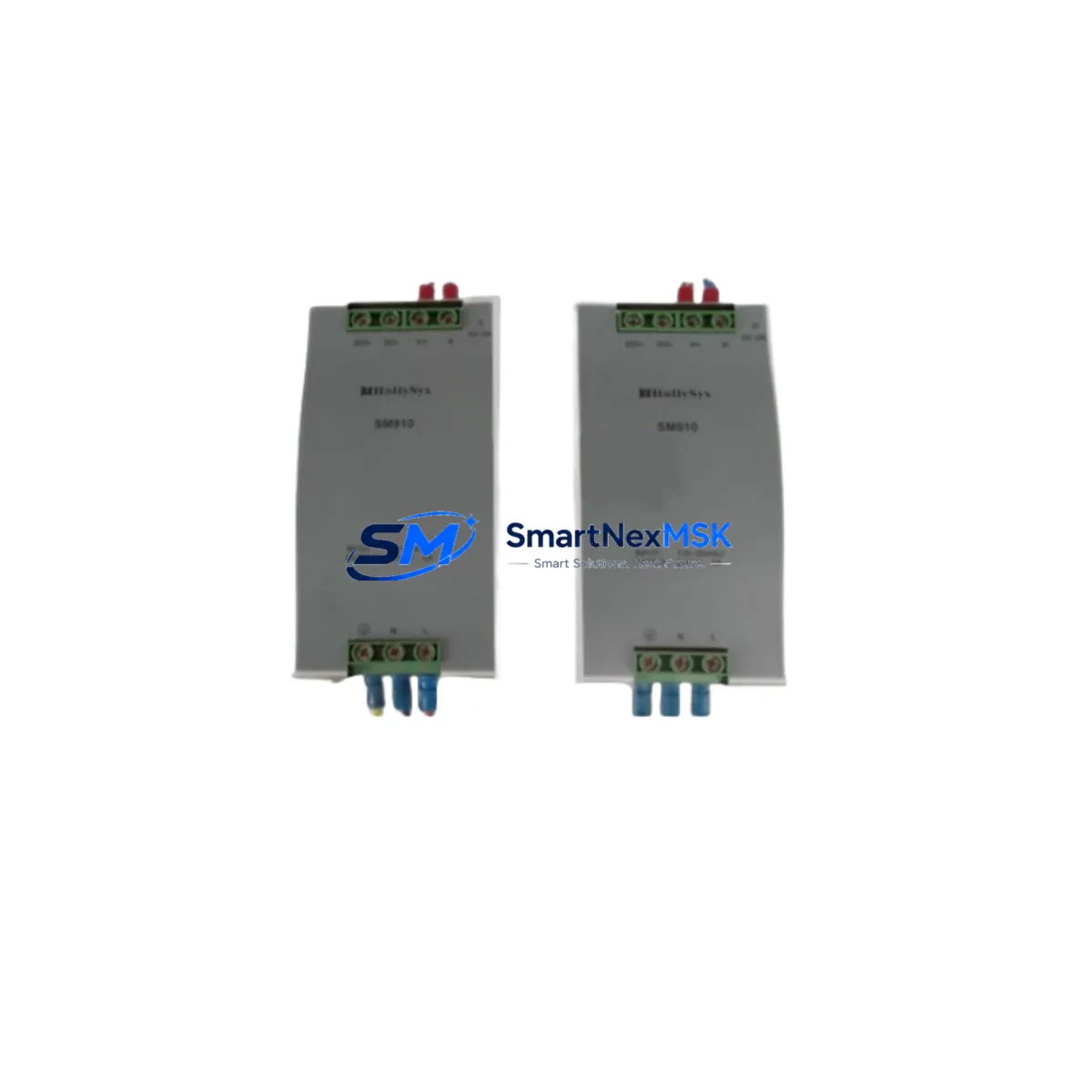
Hollysys SM910 Retrofit-Ready Power Supply for HOLLiAS DCS: Seamless Compatibility Upgrade for Legacy Control Systems
The Hollysys SM910 is a DCS power supply module engineered for retrofit deployment within HOLLiAS-series distributed control systems. As industrial facilities face increasing pressure to modernize aging infrastructure without full system replacement, the SM910 provides a validated, wiring-compatible solution that bridges legacy hardware with current operational demands. Whether you are replacing a failed unit on a running production line, upgrading a control cabinet during a planned shutdown, or migrating from an end-of-life power architecture, the SM910 is designed to minimize engineering risk and reduce total downtime.
Sourced directly from verified supply channels and tested prior to shipment, each SM910 unit is backed by a 12-month warranty covering manufacturing defects and functional failures under normal operating conditions. Stock is maintained on-hand to support urgent replacement orders, with fast dispatch available for critical plant recovery scenarios.
Upgrade Compatibility Table
| Parameter | Details |
|---|---|
| Compatible Series | Hollysys HOLLiAS DCS (MACS series and related platforms) |
| Module Type | DCS Power Supply Module |
| Replaces / Supersedes | SM910 (original), compatible with legacy HOLLiAS power bus configurations |
| Backplane Interface | HOLLiAS standard DCS backplane connector; verify slot assignment before installation |
| Terminal Wiring | Wiring-compatible with original SM910 terminal layout; confirm AC/DC input spec on-site |
| Communication Compatibility | Passive power module; no protocol configuration required |
| Installation Requirement | DIN rail or rack-mount per HOLLiAS cabinet standard; confirm chassis slot clearance |
| Commissioning Notes | Verify output voltage under load before restoring field I/O; check redundant power path if applicable |
| Replacement Recommendation | Direct drop-in for failed or end-of-life SM910 units; no firmware update required |
| Warranty | 12 months from date of shipment; covers manufacturing defects and functional failures |
Retrofit Planning for Existing Automation Systems
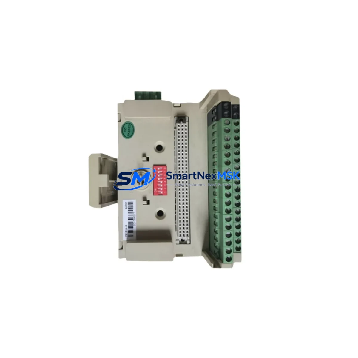
Replacing a power supply module in a live HOLLiAS DCS environment requires careful pre-work to avoid cascading failures. Before removing the existing SM910, engineers should document the current terminal wiring layout and photograph the cabinet interior for reference. Confirm that the replacement unit matches the input voltage specification — whether 220VAC or 24VDC — as mismatches can damage downstream I/O modules or the backplane itself.
In HOLLiAS MACS-based systems, the SM910 typically powers a segment of the I/O bus that feeds multiple field modules. Common co-installed components include the AI801 analog input module, DI801 digital input module, DO801 digital output module, and AO801 analog output module. These modules draw regulated DC power from the supply rail, and any voltage instability during the swap window can trigger false alarms or cause the controller — often an FM801 or FM148 main controller module — to log fault events that require manual reset.
If the system uses redundant power architecture, the SM910 may be paired with a second power module on the same chassis. In this case, the switchover to the redundant unit should be verified before the primary module is removed. Check the HOLLiAS system diagnostics via the MACS engineering workstation to confirm redundancy status. The SM148 communication module or equivalent network interface should remain online throughout the swap to preserve real-time data logging and HMI connectivity.
For cabinets that also house a Hollysys HMI terminal or operator panel, confirm that the HMI screen remains powered through an independent supply circuit. Loss of HMI visibility during a power module swap can complicate real-time monitoring. If the cabinet uses a dedicated 24VDC bus for field instruments, verify that the SM910 replacement does not share this rail — cross-contamination of power domains is a common source of post-retrofit instability.
Where the retrofit involves migrating from an older HOLLiAS generation to a current MACS-S or MACS-K platform, additional planning is required. The backplane form factor, module addressing scheme, and I/O channel mapping may differ between generations. In these cases, the SM910 power supply replacement is typically the first step in a phased upgrade that also involves swapping the FM controller, reconfiguring the SM communication module, and updating the control logic in the MACS engineering environment. Programming cables such as the HOLLiAS USB-to-RS232 adapter or Ethernet download cable are required for logic re-download after any controller replacement.
All replacement modules supplied by SMARTNEXMSK are pre-tested for output voltage accuracy and load regulation before dispatch. Each unit ships with a test report and is packaged in anti-static protection suitable for industrial handling environments.
Downtime Control During System Migration
Minimizing unplanned downtime is the primary concern in any DCS power supply replacement. The SM910 retrofit process is designed to be completed within a single planned maintenance window when proper preparation is followed. Key steps to protect operational continuity include:
First, schedule the replacement during a low-production period and notify all relevant operators. Ensure that the MACS engineering workstation has a current backup of the control program, including all function block configurations, tag assignments, and alarm setpoints. This backup protects against accidental logic loss if the controller resets during the power interruption.
Second, if the system supports hot-swap or redundant power, activate the redundant path before removing the SM910. Verify that field instruments — including pressure transmitters, flow meters, and valve positioners connected through the I/O modules — remain in their last known state during the transition. Most HOLLiAS controllers will hold output values in a configurable safe state during a brief power interruption, but this behavior should be confirmed in the system configuration before proceeding.
Third, after installing the replacement SM910, restore power gradually and monitor the output voltage on the backplane bus before reconnecting field I/O. Use the MACS diagnostic interface to confirm that all I/O modules report healthy status. Check the FM controller event log for any fault codes generated during the swap. Once all modules are confirmed online, perform a functional test of critical control loops before returning the system to automatic operation.
For systems where a full power-down is unavoidable, coordinate with the process team to place all control loops in manual mode and confirm that safety interlocks are active before beginning work. Document the start and end time of the outage for maintenance records and regulatory compliance.
Retrofit Support FAQ
Q: Is the SM910 a direct replacement for the original Hollysys SM910 installed in my HOLLiAS DCS cabinet?
A: Yes. The SM910 supplied by SMARTNEXMSK is a form-fit-function compatible replacement for the original Hollysys SM910 power supply module. It uses the same backplane connector, terminal layout, and output voltage specification. No hardware modification is required for a direct swap in standard HOLLiAS DCS configurations.
Q: Does replacing the SM910 require any changes to the control program or I/O configuration?
A: No program changes are required for a like-for-like SM910 replacement. The power supply module does not carry any addressable logic or firmware. However, if the replacement is part of a broader platform migration — for example, moving from an older HOLLiAS MACS generation to MACS-S — the controller and I/O modules may require reconfiguration, which is a separate engineering task.
Q: How do I verify wiring compatibility before installing the replacement SM910?
A: Compare the terminal block layout of the replacement unit against the existing wiring diagram for your cabinet. Confirm the input voltage type (AC or DC), the input voltage range, and the output voltage and current rating. If the original wiring diagram is unavailable, photograph the existing terminal connections before removal and use the HOLLiAS SM910 hardware manual as a reference. Contact SMARTNEXMSK technical support if you require assistance with wiring verification.
Q: What does the 12-month warranty cover, and what is the process for a warranty claim?
A: The 12-month warranty covers manufacturing defects and functional failures under normal operating conditions, including output voltage out of specification, module failure to power up, and backplane connector defects. It does not cover damage caused by incorrect installation, overvoltage, or physical impact. To initiate a warranty claim, contact SMARTNEXMSK at sales@smartnexmsk.com with your order number, a description of the fault, and photos of the installed module. Replacement units are dispatched after fault verification.
© 2026 SMARTNEXMSK. All rights reserved.
Original Source: https://smartnexmsk.com
Contact: sales@smartnexmsk.com | +86 18259474341