Hypertherm PCBS-0115/B Retrofit-Ready Axis Control Card: Compatible Modernization for Axis Control Series CNC Plasma Systems
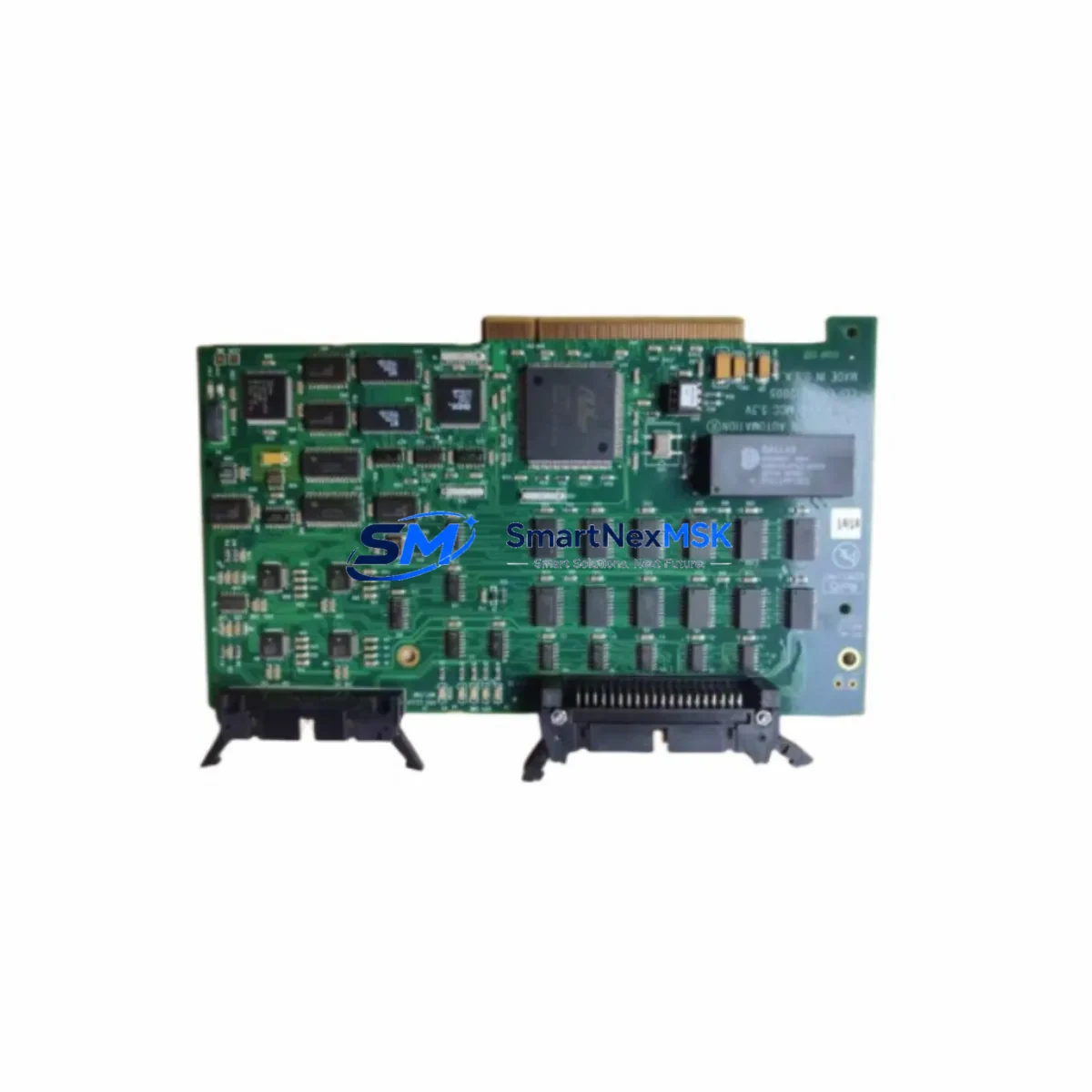
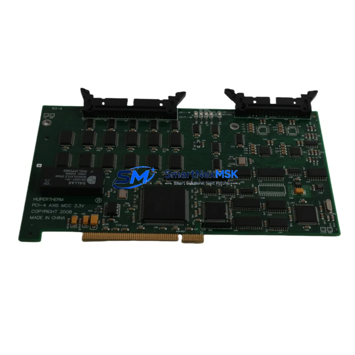
The Hypertherm PCBS-0115/B is a retrofit-ready Axis Control Card engineered for seamless integration into Hypertherm Axis Control Series CNC plasma cutting systems. As legacy motion control hardware reaches end-of-life and OEM spare parts become increasingly scarce, the PCBS-0115/B provides a verified, drop-in replacement path that preserves existing machine logic, minimizes downtime, and extends the productive service life of your cutting line. Whether you are managing a planned upgrade cycle or responding to an unplanned board failure, this module is pre-tested, warehouse-stocked, and backed by a 12-month warranty.
Industrial facilities operating Hypertherm Axis Control Series plasma tables — including older HT series and MAX series cutting platforms — frequently encounter obsolescence challenges with the original motion control PCB. The PCBS-0115/B addresses this directly by maintaining full electrical and functional compatibility with the original backplane connector layout, axis drive interface, and encoder feedback circuits. Technicians can remove the failed board, seat the PCBS-0115/B into the same card slot, restore the original parameter file, and return the machine to production without rewriting PLC logic or modifying the control cabinet wiring harness.
Upgrade Compatibility Table
| Parameter | Detail |
|---|---|
| Replaced / Superseded Part | Hypertherm PCBS-0115/B (OEM original) |
| Compatible Series | Hypertherm Axis Control Series, HT Series CNC Plasma Platforms |
| Backplane Interface | Direct plug-in; matches original card-edge connector pitch and pinout |
| Axis Drive Communication | Compatible with existing servo amplifier and stepper drive wiring |
| Encoder Feedback | Supports standard quadrature encoder inputs; no re-parameterization required |
| Power Supply Requirement | Verify control cabinet DC bus voltage (typically +5 VDC / ±12 VDC) before installation |
| Communication Protocol | Compatible with existing RS-232 / RS-422 HMI and operator panel links |
| Installation Requirement | ESD precautions required; power-down and lockout/tagout before card swap |
| Commissioning | Restore axis parameter file; verify home position, soft limits, and feed rate scaling |
| Warranty | 12 months from date of shipment; covers manufacturing defects |
Retrofit Planning for Existing Automation Systems
A successful PCBS-0115/B retrofit begins well before the replacement card arrives on site. Maintenance engineers should audit the full control cabinet to identify all interdependent components that may require attention during the same service window. In a typical Hypertherm Axis Control Series installation, the motion control PCB works in close coordination with the system power supply module, which must be verified to deliver stable regulated DC rails within the tolerance band specified for the PCBS-0115/B. A degraded or undersized power supply is one of the most common root causes of repeated axis card failures, and replacing the PCB without addressing the upstream power quality will result in premature re-failure.
The I/O interface board, which routes discrete signals between the CNC controller and the cutting table’s limit switches, torch height control, and plasma arc start relay, should be inspected for corrosion, cracked solder joints, and worn terminal blocks. Similarly, the communication module responsible for linking the CNC controller to the operator HMI panel — often using an RS-232 or RS-422 serial link — should be confirmed operational before the new axis card is commissioned, since a faulty communication link can produce misleading axis fault codes that are difficult to distinguish from a hardware PCB failure.
For facilities that have already migrated their cutting programs to a modern G-code post-processor or CAM platform, the retrofit is also an opportunity to verify that the axis scaling parameters stored in the controller’s non-volatile memory are consistent with the current machine geometry. If the original PCBS-0115/B failed catastrophically, the parameter file may need to be restored from a backup or re-entered manually. Engineers should have the machine’s axis pitch, gear ratio, encoder resolution, and maximum velocity values documented before beginning the swap.
The backplane rack and card cage should be inspected for bent guide rails, damaged ejector levers, and contamination from coolant mist or metal dust — all common in plasma cutting environments. The torch height control card, plasma arc voltage feedback module, and any auxiliary I/O expansion cards seated in adjacent slots should be removed, cleaned, and reseated during the same maintenance window to ensure reliable backplane contact. If the system uses a dedicated motion network card for coordinating multi-axis gantry movement, its firmware version should be confirmed compatible with the replacement PCBS-0115/B before power-up.
Facilities planning a broader control system modernization — for example, migrating from the legacy Axis Control Series platform to a current-generation CNC controller — can use the PCBS-0115/B as a bridge solution to keep the existing machine productive while the new control system is being engineered, sourced, and staged. This approach avoids the cost and risk of a forced emergency cutover and allows the engineering team to complete the full migration on a planned schedule.
Downtime Control During System Migration
Unplanned axis card failures in plasma cutting operations typically result in immediate production stoppage, since the cutting table cannot execute motion commands without a functional axis control board. The PCBS-0115/B is warehouse-stocked to support same-day or next-business-day dispatch, which is the single most effective measure for minimizing unplanned downtime in legacy system environments where OEM spare parts are no longer available through standard distribution channels.
For planned maintenance windows, the recommended procedure is to power down the control cabinet using the established lockout/tagout protocol, photograph the existing wiring and card positions before removal, extract the failed or suspect PCBS-0115/B, install the replacement card in the same slot, restore the axis parameter file from the backup copy, and perform a controlled jog test on each axis before returning the machine to automatic cycle. The entire procedure can typically be completed within two to four hours by a qualified CNC maintenance technician, provided the parameter backup is available and no secondary faults are present in the drive or feedback wiring.
To protect the original program logic during the migration, the CNC part programs stored in the controller’s memory should be backed up to an external USB drive or network share before any hardware work begins. If the controller uses a battery-backed SRAM for program storage, the battery condition should be checked and replaced if necessary, since a low battery can cause program loss during power cycling. The HMI operator panel screens and any custom macro programs should also be documented, as these may need to be reloaded if the controller memory is cleared during the card replacement process.
After the PCBS-0115/B is installed and the axis parameters are restored, the commissioning sequence should include a full-travel jog test on each axis to verify correct direction, speed, and limit switch response; a reference-point return cycle to confirm the home position is correctly established; and a dry-run of a representative cutting program with the plasma torch disabled to verify that the motion profile executes correctly before live cutting resumes.
Retrofit Support FAQ
Q1: Is the PCBS-0115/B a direct drop-in replacement for the original Hypertherm Axis Control Series board?
Yes. The PCBS-0115/B is designed to match the original card-edge connector, mounting dimensions, and electrical interface of the Hypertherm Axis Control Series axis control board. No modifications to the backplane, wiring harness, or control cabinet are required for a standard replacement. Axis parameters should be restored from the existing backup file after installation.
Q2: What pre-installation checks should be completed before fitting the replacement card?
Before installing the PCBS-0115/B, verify that the control cabinet power supply module is delivering stable DC rails within specification, inspect the backplane connector for bent pins or contamination, confirm that the axis drive wiring and encoder cables are undamaged, and ensure that a current backup of the axis parameter file is available. These steps prevent secondary failures and reduce commissioning time.
Q3: Can the PCBS-0115/B be used in a system that has been partially upgraded with newer I/O or communication modules?
In most cases, yes. The PCBS-0115/B is compatible with the standard backplane interface used across the Hypertherm Axis Control Series, which means it can coexist with upgraded I/O expansion cards, replacement communication modules, or updated torch height control cards installed in adjacent slots. If the system has undergone significant hardware changes, contact our technical team before ordering to confirm compatibility with your specific configuration.
Q4: What does the 12-month warranty cover, and what is the process for a warranty claim?
The 12-month warranty covers manufacturing defects in materials and workmanship from the date of shipment. It does not cover damage resulting from incorrect installation, electrostatic discharge, overvoltage events, or physical impact. To initiate a warranty claim, contact sales@smartnexmsk.com with your order number, a description of the fault symptom, and photographs of the installed card and surrounding wiring. Our team will arrange a replacement or repair within the warranty period.
© 2026 SMARTNEXMSK. All rights reserved.
Original Source: https://smartnexmsk.com
Contact: sales@smartnexmsk.com | +86 18259474341