ICS ICST3510 Retrofit-Ready I/O Power Supply for T3000 DCS Control Systems
The ICS ICST3510 is a retrofit-ready I/O power supply module engineered for seamless integration into legacy T3000 Distributed Control System (DCS) architectures. As original ICS T3000 series components approach end-of-life and OEM supply channels close, the ICST3510 remains a critical backbone for sustaining field-proven control loops, I/O marshalling cabinets, and distributed process automation networks. SMARTNEXMSK maintains verified stock of the ICST3510 with full functional testing, 12-month warranty coverage, and rapid global dispatch from our Xiamen warehouse.
Whether you are executing a planned control system upgrade, responding to an unplanned module failure, or consolidating spare parts inventory ahead of a plant turnaround, the ICST3510 delivers the electrical stability and backplane compatibility required to keep your T3000 DCS running without forced migration to a new platform. Our engineering team has supported ICST3510 retrofits across petrochemical, power generation, water treatment, and discrete manufacturing environments.
Upgrade Compatibility Table
| Parameter | Detail |
|---|---|
| Module Model | ICS ICST3510 (T3510) |
| Series Compatibility | ICS T3000 DCS — T3100, T3200, T3400, T3500, T3510, T3600 subsystems |
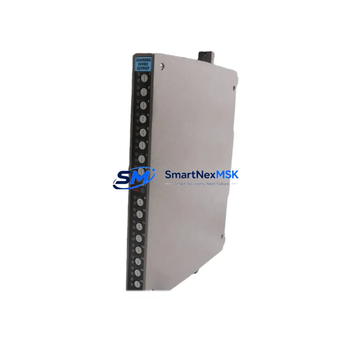
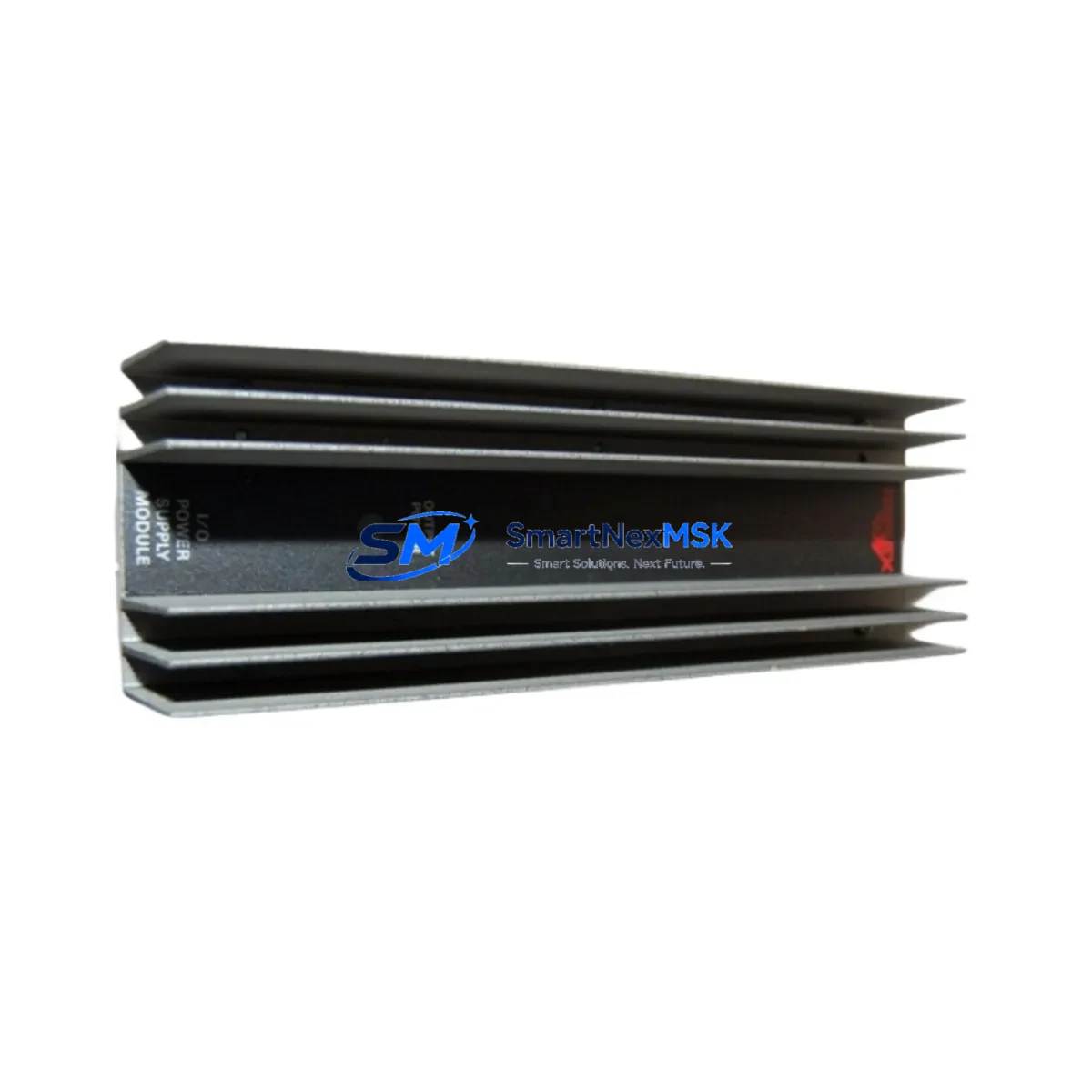
| Module Function | I/O Power Supply — provides regulated DC power to I/O termination assemblies and field wiring modules |
| Backplane Interface | T3000-series DIN-rail or rack backplane; direct slot replacement, no adapter required |
| Terminal Wiring | Compatible with existing T3000 field wiring harnesses; no re-termination required under standard retrofit conditions |
| Communication Compatibility | Transparent to T3000 communication bus (MODBUS RTU / proprietary ICS fieldbus); no protocol reconfiguration needed |
| Replacement Recommendation | Direct drop-in for failed or end-of-life ICST3510 units; verify power rail loading before installation |
| Commissioning Notes | Confirm module address DIP switch settings match original; validate I/O channel scan in DCS engineering workstation post-swap |
| Installation Requirement | De-energize affected I/O rack segment; follow ICS T3000 maintenance manual lockout/tagout procedure |
| Warranty | 12-Month Warranty — covers manufacturing defects and functional failure under normal operating conditions |
Retrofit Planning for Existing Automation Systems
A successful ICST3510 retrofit begins well before the module arrives on site. During the pre-engineering phase, technicians should audit the full T3000 DCS cabinet layout, documenting the position of each I/O power supply slot, the associated I/O termination assemblies, and the field wiring marshalling arrangement. In a typical T3000 installation, the ICST3510 shares a rack with multiple I/O modules — such as analog input cards, digital output cards, and thermocouple input modules — all of which draw regulated power from the supply rail. Confirming that the replacement ICST3510 can sustain the aggregate load of all co-resident I/O cards is the first critical checkpoint.
The T3000 DCS backplane uses a proprietary slot-and-connector architecture. Before ordering, verify that the target rack generation (T3100 or T3500 sub-chassis variants) uses the same backplane pinout as the ICST3510 specification sheet. In mixed-generation cabinets — common in plants that have expanded incrementally — you may find T3200 I/O expansion racks alongside original T3100 controller racks, each with slightly different power distribution schemes. The ICST3510 is rated for the standard T3000 power bus; consult your as-built drawings to confirm compatibility across all rack generations present in the cabinet.
Communication continuity is another key concern. The T3000 DCS controller — typically a T3600 or T3400 master controller unit — communicates with I/O racks over a dedicated fieldbus segment. The ICST3510 power supply is transparent to this communication layer, meaning a module swap does not interrupt the fieldbus scan cycle provided the replacement is installed and powered within the controller’s configurable I/O timeout window. For systems using a MODBUS RTU gateway or a legacy ICS proprietary communication interface, confirm that the DCS engineering workstation retains the original I/O map and that no forced re-download of the controller program is required after the swap.
Field wiring integrity should be verified before re-energizing the rack. In older T3000 installations, the I/O termination assembly — a passive wiring board that connects field cables to the active I/O module — may show signs of terminal oxidation or loose screw connections after years of service. This is an ideal time to inspect and re-torque all field terminals, replace any degraded terminal blocks, and verify cable labelling against the loop drawings. If the plant uses a T3000-compatible HMI — such as a legacy ICS operator workstation or a third-party SCADA system connected via OPC-DA — confirm that the HMI tag database reflects the correct I/O channel assignments before returning the loop to automatic control.
For plants planning a broader control system modernization, the ICST3510 retrofit can serve as a bridge strategy: stabilize the existing T3000 DCS with verified spare modules while engineering resources are allocated to a phased migration toward a modern DCS or PLC platform. In this context, the ICST3510 extends the operational life of the T3000 infrastructure by three to five years, providing time for a structured migration that avoids forced emergency replacements and the associated unplanned downtime costs.
Downtime Control During System Migration
Minimizing downtime during an ICST3510 swap requires a structured hot-swap or cold-swap procedure depending on the T3000 rack design. For racks that support individual I/O segment isolation — where a dedicated power feed breaker serves a single I/O rack — the affected rack can be de-energized while adjacent racks remain in service, limiting the control impact to the I/O points served by that rack. Before de-energizing, place all affected control loops in manual mode at the DCS operator workstation, confirm with field operators that process conditions are stable, and document the current output states of all digital output channels in the affected rack.
The physical module swap is typically completed in under fifteen minutes: remove the failed ICST3510, verify the replacement module’s DIP switch address settings match the original, seat the new module firmly into the backplane connector, and restore power to the rack segment. The T3000 DCS controller will automatically re-scan the I/O rack upon power restoration; monitor the engineering workstation for any I/O fault alarms and confirm that all analog and digital channels return to healthy status before returning loops to automatic control.
To protect the original controller program logic, do not perform a full program download during the swap unless a firmware mismatch is detected. The T3000 controller retains its program in non-volatile memory; a rack power cycle does not erase the control logic. If the DCS engineering workstation prompts for a program comparison after the swap, perform an online compare rather than a forced download to avoid overwriting any unsaved online edits made by field engineers during the outage. Total planned downtime for a single ICST3510 swap in a well-prepared T3000 system is typically thirty to sixty minutes, including pre-swap loop-to-manual transfer and post-swap loop-to-auto verification.
Retrofit Support FAQ
Q1: Is the ICST3510 a direct drop-in replacement for the original ICS T3510 module?
Yes. The ICST3510 is the manufacturer’s own part number for the T3510 I/O power supply module. It uses the same backplane connector, the same power rail output specification, and the same DIP switch address scheme as the original. No wiring modifications or software changes are required for a like-for-like replacement in a standard T3000 DCS rack.
Q2: How do I verify the module address settings before installation?
Locate the DIP switch bank on the face of the original ICST3510 before removal and photograph the switch positions. The replacement module ships with all switches in the default (OFF) position. Set the switches on the replacement to match the original configuration before inserting the module into the backplane. Refer to the ICS T3000 I/O Module Addressing Guide for the address map corresponding to your rack slot position.
Q3: What pre-shipment testing does SMARTNEXMSK perform on the ICST3510?
Every ICST3510 unit undergoes functional power-on testing, output voltage verification across all regulated rails, and visual inspection for connector pin integrity and PCB condition before dispatch. Units that pass testing are issued a test certificate and shipped with anti-static packaging. The 12-month warranty covers any functional failure arising from manufacturing defects or latent component faults under normal operating conditions.
Q4: Can the ICST3510 be used in a T3000 system that has been partially upgraded to a newer I/O platform?
Yes, provided the T3000 backplane and power bus architecture in the target rack has not been modified. In hybrid cabinets where some racks have been upgraded to a newer ICS or third-party I/O platform while others retain the original T3000 architecture, the ICST3510 continues to function correctly in the unmodified T3000 racks. Confirm that the power bus voltage and current capacity of the target rack are within the ICST3510’s rated operating range before installation.
© 2026 SMARTNEXMSK. All rights reserved.
Original Source: https://smartnexmsk.com
Contact: sales@smartnexmsk.com | +86 18259474341