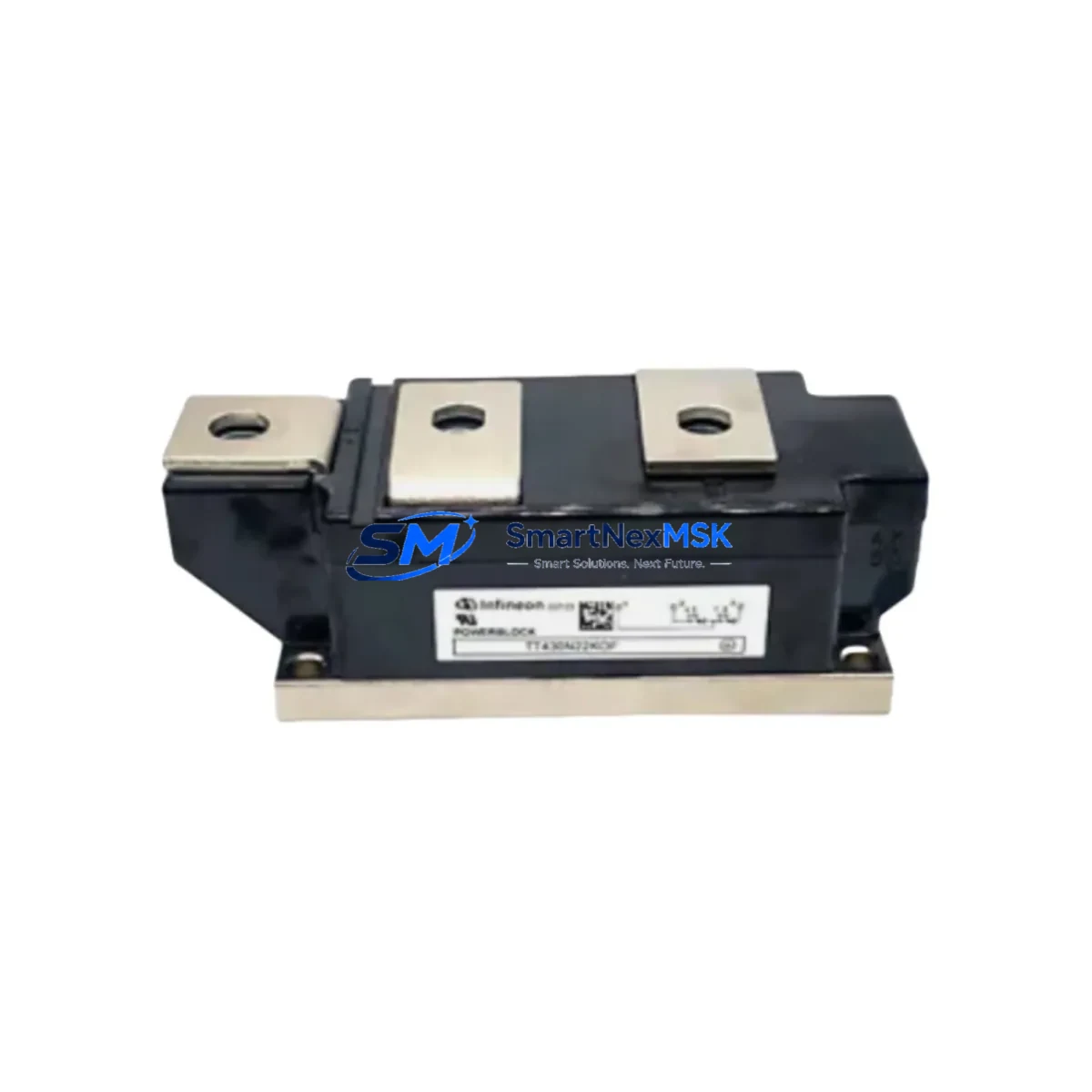
Infineon DD180N16S Retrofit-Ready Rectifier Diode for DD-Series Control Systems
The Infineon DD180N16S is a 180A / 1600V press-pack rectifier diode module engineered for seamless integration into legacy DD-series drive systems, industrial rectifier bridges, and DC bus assemblies. As original DD-series components reach end-of-life or become increasingly difficult to source, the DD180N16S provides a verified drop-in retrofit path that preserves existing wiring layouts, mounting footprints, and thermal management configurations — minimising engineering rework and unplanned downtime.
Whether you are modernising a thyristor-based DC drive cabinet, replacing a failed rectifier stage in a crane hoist controller, or upgrading the front-end power section of a legacy variable-speed drive, the DD180N16S delivers the electrical performance and mechanical compatibility required for a reliable, long-service retrofit.
Upgrade Compatibility Table
| Parameter | DD180N16S Specification | Retrofit Notes |
|---|---|---|
| Rated Current (ITAV) | 180 A | Verify existing heatsink thermal resistance; derate if ambient >40 °C |
| Repetitive Peak Voltage (VRRM) | 1600 V | Suitable for 690 V AC input rectifier bridges; confirm DC bus voltage headroom |
| Mounting Interface | Press-pack / stud mount | Match torque spec (typically 25–35 Nm); use original copper bus bar if possible |
| Thermal Interface | Direct copper base to heatsink | Apply fresh thermal compound; inspect heatsink flatness before installation |
| Communication Compatibility | N/A (passive power component) | No firmware or protocol changes required |
| Replacement Scope | DD-series rectifier diode positions | Confirm polarity marking (cathode stud vs. anode stud variants) |
| Commissioning Requirement | Torque, insulation test, forward-voltage check | Perform diode forward-voltage drop test (0.7–1.1 V typical) before energising |
| Warranty | 12 Months | Covers manufacturing defects; full test report available on request |
Retrofit Planning for Existing Automation Systems
A successful DD180N16S retrofit begins well before the module arrives on site. Engineers should first audit the complete rectifier bridge assembly — typically a six-pulse or twelve-pulse configuration — and document the condition of companion components. In many DD-series cabinets, the rectifier diodes share a common heatsink assembly with Infineon TT250N16KOF thyristor modules or similar SCR devices used for soft-start or phase control. If one diode has failed due to overcurrent or thermal stress, it is best practice to replace the full bridge set simultaneously to avoid mismatched forward-voltage characteristics that can cause unequal current sharing.
The DC bus capacitor bank — often comprising large electrolytic capacitors rated at 1800 µF / 450 V or higher — should be inspected for ESR drift and capacitance loss, particularly in systems older than eight years. A degraded capacitor bank will stress the replacement diode during inrush events. Similarly, the DC bus fuse (typically a semiconductor-grade fast-acting fuse such as a Bussmann 170M series) must be verified for correct current rating and replaced if it shows any signs of thermal discolouration.
On the AC input side, confirm that the input line reactor or AC choke — commonly a 3-phase reactor rated at 2–5% impedance — is intact and correctly sized for the drive’s kVA rating. A faulty or undersized reactor will expose the DD180N16S to excessive di/dt stress during commutation. If the existing system uses a Siemens SIMOREG DC Master or an ABB DCS800 DC drive controller, the rectifier bridge is a field-replaceable assembly and the DD180N16S can be installed without any changes to the drive’s control board, firing circuit, or parameter set.
For systems that include a Eurotherm 590+ DC drive or similar analogue-controlled DC drive, the firing angle and current limit parameters stored in the drive’s non-volatile memory remain unaffected by a diode replacement. However, it is advisable to perform a no-load run and verify armature current feedback via the drive’s diagnostic display or a clamp meter before resuming full production load.
Where the rectifier feeds a DC motor field supply in addition to the armature circuit, ensure the field rectifier — often a separate single-phase bridge using smaller diodes such as the Infineon DD55N or DD91N series — is also inspected. A field supply failure during commissioning can cause field weakening faults that are easily misdiagnosed as a rectifier problem.
Wiring and terminal adaptation is straightforward: the DD180N16S uses the same stud-mount interface as its predecessors, so existing copper bus bars, flexible braided connectors, and torque-critical fasteners can be reused provided they are in good condition. Label all connections before disassembly and photograph the original wiring layout. Confirm that the gate/base drive board (if present for thyristor positions in the same assembly) is isolated before handling any power semiconductor.
All units supplied by SMARTNEXMSK are pre-tested for forward voltage drop, reverse leakage current, and insulation integrity. Each DD180N16S ships with a test certificate and is covered by a 12-month warranty against manufacturing defects.
Downtime Control During System Migration
Minimising production downtime during a rectifier diode replacement requires a structured pre-outage preparation plan. Begin by ordering the DD180N16S and all ancillary consumables — thermal compound, replacement fuses, insulation test equipment, and torque wrench — at least one week before the scheduled maintenance window. Confirm that a spare Infineon DD180N16S is held on-site if the system is critical to continuous production.
On the day of the outage, follow a strict lockout/tagout (LOTO) procedure and allow the DC bus capacitors to fully discharge — typically 5–10 minutes after isolation, confirmed by a calibrated voltmeter reading below 50 V DC. Do not rely on the drive’s internal discharge resistor alone.
The physical swap of a press-pack diode module typically takes 20–40 minutes for an experienced technician. The majority of retrofit time is consumed by insulation testing, torque verification, and the initial no-load commissioning run. By preparing a commissioning checklist in advance — covering torque values, insulation resistance targets (>1 MΩ at 500 V DC), forward-voltage readings, and first-energisation current limits — teams can complete the full retrofit and return the system to production within a 2–4 hour maintenance window.
Where the process cannot tolerate even a brief outage, consider a parallel redundancy strategy: install a bypass contactor across the rectifier bridge during the swap, maintaining DC bus voltage from an alternative source such as a battery-backed UPS module or a second rectifier feed. This approach is common in continuous-process industries such as paper mills, aluminium smelters, and chemical plants where DC drive systems run 24/7.
After re-energisation, monitor the heatsink temperature of the new DD180N16S under full load for the first 30 minutes using a non-contact infrared thermometer. A stable heatsink temperature within the manufacturer’s specified range confirms a successful retrofit. Log the commissioning data for future reference and update the site’s maintenance records accordingly.
Retrofit Support FAQ
Q1: Is the DD180N16S a direct drop-in replacement for all DD-series rectifier positions?
The DD180N16S is dimensionally and electrically compatible with the majority of DD-series 180 A / 1600 V rectifier positions. However, always verify the polarity orientation (cathode-stud vs. anode-stud) and confirm the exact part number of the module being replaced. If you are replacing a lower-rated DD-series diode (e.g., DD91N or DD130N), the DD180N16S can be used as an uprated substitute, but confirm that the heatsink and bus bar are rated for the higher current capacity.
Q2: What commissioning tests are required after installation?
Perform an insulation resistance test (>1 MΩ at 500 V DC between anode/cathode and heatsink), a forward-voltage drop test (0.7–1.1 V at low current), and a visual inspection of all torqued connections. After energisation, verify DC bus voltage is within expected range and monitor heatsink temperature under load for the first 30 minutes.
Q3: Can I reuse the existing wiring and bus bars?
Yes, in most cases. The DD180N16S uses the same stud-mount interface as standard DD-series diodes. Inspect all copper bus bars for cracks, corrosion, or heat discolouration before reuse. Replace any flexible braided connectors that show signs of fatigue or oxidation. Re-torque all connections to the specified value using a calibrated torque wrench.
Q4: What does the 12-month warranty cover?
The 12-month warranty covers manufacturing defects in materials and workmanship. Each unit is tested prior to shipment and ships with a test certificate. Warranty claims require the original test certificate and a description of the failure mode. Damage caused by incorrect installation, overvoltage, or failure to follow commissioning procedures is not covered. Contact sales@smartnexmsk.com for warranty support.
© 2026 SMARTNEXMSK. All rights reserved.
Original Source: https://smartnexmsk.com
Contact: sales@smartnexmsk.com | +86 18259474341