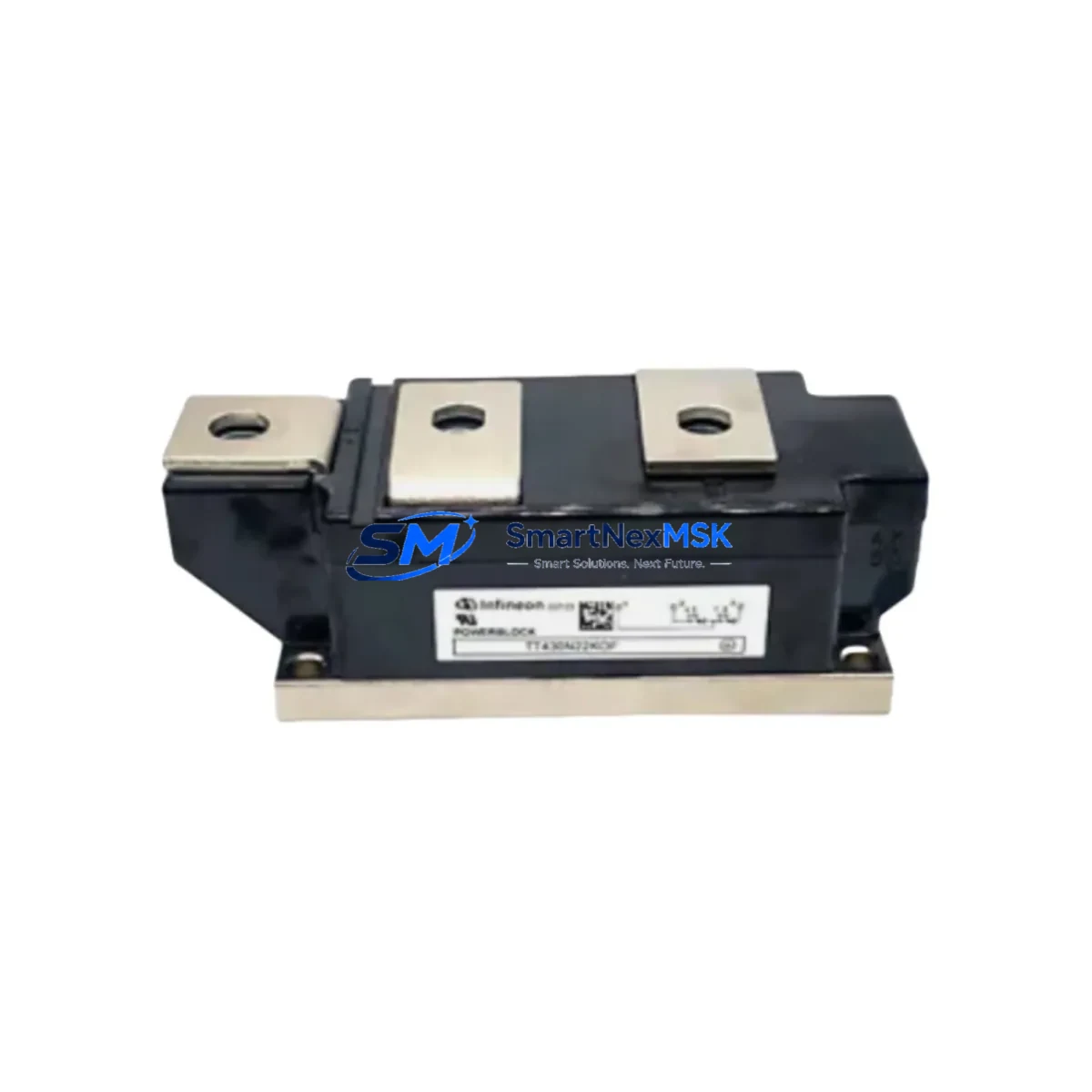
INFINEON TT430N22KOF Spare for SEMIPACK3 Automation
The INFINEON TT430N22KOF is a dual SCR (Silicon Controlled Rectifier) thyristor module in the SEMIPACK3 package, rated at 430A average on-state current and 2200V repetitive peak off-state voltage. As a maintenance-ready spare, it is engineered to support rapid field replacement in industrial power conversion systems, motor drives, soft starters, and rectifier bridges where unplanned downtime carries significant operational and financial risk. Sourced as an original component, each unit is tested prior to dispatch and backed by a 12-month warranty, ensuring confidence for both planned maintenance cycles and emergency breakdown recovery.
For maintenance engineers managing aging drive systems, crane controls, rolling mill drives, or large HVAC power stages, the TT430N22KOF represents a critical line-replaceable unit (LRU). Its SEMIPACK3 footprint is widely adopted across Siemens, ABB, and Fuji Electric drive platforms, making it a versatile spare that consolidates inventory across multiple system types. Procurement engineers can stock this module with confidence, knowing it covers a broad compatibility matrix without requiring platform-specific variants.
Spare Maintenance Table
| Parameter | Specification |
|---|---|
| Part Number | TT430N22KOF |
| Brand | INFINEON (formerly Eupec) |
| Package | SEMIPACK3 |
| Configuration | Dual SCR (Common Cathode) |
| Average On-State Current (IT(AV)) | 430 A |
| Repetitive Peak Voltage (VDRM/VRRM) | 2200 V |
| On-State Voltage (VT) | ≤ 1.55 V @ IT = 430 A |
| Gate Trigger Current (IGT) | ≤ 150 mA |
| Operating Temperature | -40°C to +125°C (Tj) |
| Mounting | Baseplate, M6 screw |
| Cooling | Heatsink required (forced air or liquid) |
| Compatibility | SEMIPACK3 footprint; replaces TT430N22, TT430N22L, TT430N22KOF variants |
| Application | AC/DC drives, rectifiers, soft starters, crane controls, UPS |
| Origin | Germany |
| Warranty | 12 Months |
| Pre-shipment Test | Yes — electrical parameters verified before dispatch |
Maintenance Planning for Continuous Operation
When replacing the TT430N22KOF in a live industrial environment, a disciplined maintenance approach extends well beyond the thyristor module itself. Maintenance engineers should treat this replacement as an opportunity to audit the entire power conversion stack within the control cabinet.
Begin with the DC bus fuse or semiconductor fuse (e.g., Bussmann 170M series or equivalent) mounted in series with the thyristor bridge. A failed thyristor frequently causes fuse rupture, and installing a new TT430N22KOF without replacing a suspect fuse risks immediate re-failure. Inspect the snubber RC network (resistor-capacitor circuit) connected across each SCR — degraded snubbers are a leading cause of premature thyristor failure due to dV/dt stress.
Check the gate driver board or firing card that supplies trigger pulses to the TT430N22KOF. Weak or asymmetric gate signals cause partial conduction and thermal runaway. In Siemens SIMOREG or ABB DCS800 platforms, this is typically a dedicated pulse transformer board. Verify the heatsink thermal interface: clean the baseplate contact surface, apply fresh thermal compound, and confirm heatsink fin condition and fan operation — the TT430N22KOF’s 430A rating demands effective thermal management.
Inspect the AC input contactor and line reactor upstream of the rectifier bridge. Worn contactor contacts introduce resistance that stresses the thyristor during inrush. Review the current transformer (CT) and overcurrent relay settings — these protect the thyristor bridge and must be calibrated to the module’s current rating. For systems with a DC link capacitor bank, measure capacitance and ESR; aged capacitors increase ripple current through the thyristors.
On the control side, verify the PLC or DCS analog output card providing the speed or current reference signal to the drive. A drifting output card can cause the drive to demand excessive current, stressing the thyristor bridge. Check terminal blocks and bus bars for signs of overheating, loose connections, or corrosion — high-resistance joints are a silent cause of thyristor stress. If the system includes a signal isolator or transducer for current or voltage feedback, confirm its calibration, as incorrect feedback can destabilize the control loop and cause thyristor overcurrent events.
For older systems approaching end-of-life, consider stocking a complete rectifier bridge assembly or a matched set of thyristor modules alongside the TT430N22KOF to enable full bridge replacement during a planned shutdown, minimizing future emergency downtime.
Site Replacement Workflow
Step 1 — Isolation and Lockout/Tagout (LOTO): De-energize the drive system, discharge the DC bus capacitors (verify with a calibrated voltmeter — allow minimum 5 minutes), and apply LOTO per site safety procedures.
Step 2 — Document and photograph: Record gate wiring connections, bus bar positions, and torque marks on the existing TT430N22KOF before removal. Photograph the heatsink contact surface condition.
Step 3 — Remove the failed module: Loosen M6 mounting screws in a cross pattern to avoid baseplate distortion. Disconnect gate and cathode leads, noting polarity and wire labeling.
Step 4 — Prepare the heatsink: Clean the heatsink surface with isopropyl alcohol. Apply a thin, uniform layer of thermal interface compound. Inspect for surface damage or warping.
Step 5 — Install the TT430N22KOF: Position the module, hand-tighten M6 screws, then torque to manufacturer specification (typically 4–6 Nm). Reconnect gate and cathode leads per the original documentation.
Step 6 — Pre-power verification: Measure gate-cathode resistance on both SCR elements (should be low, typically 5–50 Ω). Verify anode-cathode blocking voltage with a multimeter in diode mode. Confirm no short circuit across the DC bus.
Step 7 — Controlled power-up: Re-energize with the drive in a no-load or reduced-load condition. Monitor heatsink temperature, gate firing symmetry, and output current balance across all phases during initial operation.
Step 8 — Return to service: Log the replacement in the maintenance management system (CMMS), update the spare parts inventory, and schedule the next inspection interval per the drive manufacturer’s maintenance schedule.
This workflow is applicable to direct replacements of legacy Eupec TT430N22 and TT430N22L modules, which share the same SEMIPACK3 footprint and electrical ratings, enabling seamless substitution without drive parameter changes.
Spare Parts Support FAQ
Q1: What is the shelf life of the TT430N22KOF in storage, and how should it be stored?
The TT430N22KOF has an indefinite shelf life when stored correctly. Keep the module in its original anti-static packaging in a dry environment at 15–35°C with relative humidity below 75% (non-condensing). Avoid storage near strong magnetic fields or corrosive atmospheres. Inspect the baseplate and terminals for oxidation before installation if stored for more than 12 months.
Q2: How do I confirm compatibility before installation in my specific drive platform?
Confirm the SEMIPACK3 mounting footprint (baseplate dimensions and M6 screw pattern), the voltage class (2200V VDRM/VRRM), and the current rating (430A IT(AV)) match your existing module’s datasheet. The TT430N22KOF is a direct functional replacement for TT430N22 and TT430N22L variants. For Siemens SIMOREG, ABB DCS800, or similar platforms, cross-reference the drive’s spare parts list or contact our technical team with your drive model number.
Q3: What pre-shipment testing is performed on each TT430N22KOF unit?
Each unit undergoes electrical parameter verification prior to dispatch, including forward blocking voltage, reverse blocking voltage, gate trigger current, and on-state voltage drop. Units that do not meet INFINEON datasheet specifications are rejected. A test report is available upon request for critical applications.
Q4: What does the 12-month warranty cover, and what is the claims process?
The 12-month warranty covers manufacturing defects and electrical parameter non-conformance under normal operating conditions. It does not cover damage resulting from incorrect installation, overvoltage events, or operation outside rated parameters. To initiate a warranty claim, contact sales@smartnexmsk.com with the order number, installation date, and a description of the failure mode. Replacement or refund is processed within 5–10 business days upon receipt and inspection of the returned unit.
© 2026 SMARTNEXMSK. All rights reserved.
Original Source: https://smartnexmsk.com
Contact: sales@smartnexmsk.com | +86 18259474341