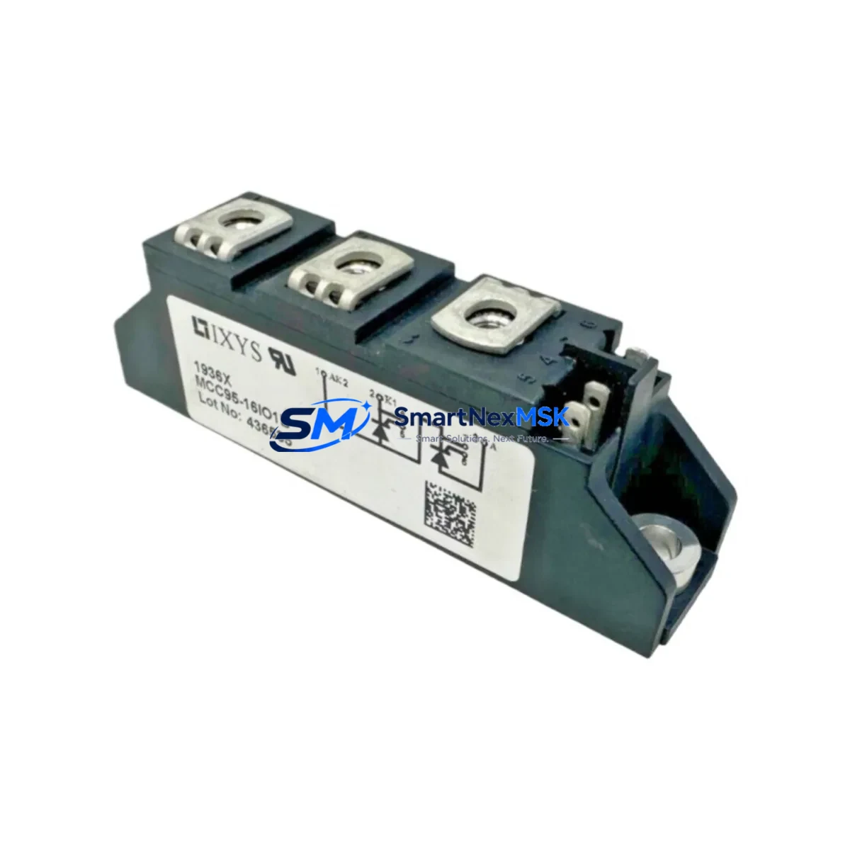
IXYS MCC95-16IO1B Retrofit-Ready SCR Thyristor for MCC Series Control Systems
The IXYS MCC95-16IO1B is a 95A / 1600V phase-controlled SCR thyristor module engineered for seamless integration into legacy MCC Series power conversion and motor drive systems. As original MCC-family components reach end-of-life or become increasingly difficult to source, the MCC95-16IO1B provides a verified, drop-in compatible retrofit path that preserves existing wiring layouts, mounting footprints, and control logic — minimising engineering rework and unplanned downtime on the production floor.
Manufactured to IXYS quality standards and supplied with a 12-month warranty, each unit undergoes outgoing electrical testing covering forward blocking voltage, gate trigger current, holding current, and thermal resistance before shipment. Stock is maintained for immediate dispatch to support urgent replacement and scheduled maintenance windows alike.
Upgrade Compatibility Table
| Parameter | MCC95-16IO1B | Retrofit Notes |
|---|---|---|
| Rated Current (ITAV) | 95 A | Verify heatsink thermal capacity matches original design |
| Blocking Voltage (VRRM) | 1600 V | Suitable for 690 VAC three-phase drive applications |
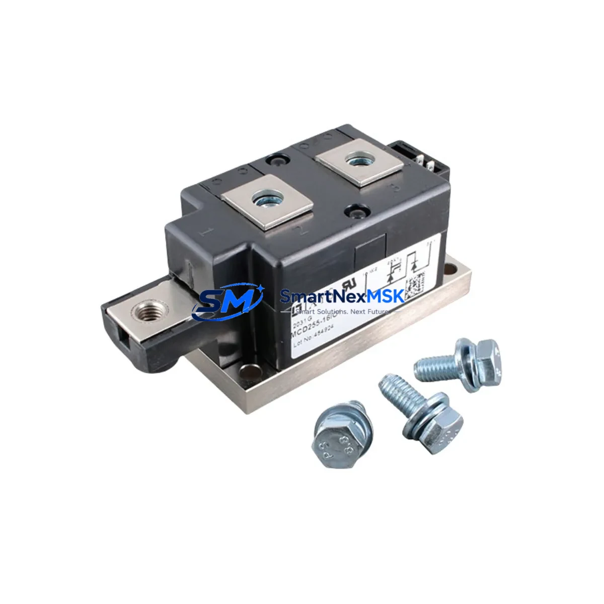
| Package / Mounting | Standard MCC isolated base, M5 terminals | Direct bolt-in replacement; no bracket modification required |
| Gate Trigger Current (IGT) | ≤ 150 mA | Compatible with existing gate driver boards in MCC Series cabinets |
| Thermal Interface | Isolated copper base plate | Re-apply thermal compound; torque M5 bolts to 3 N·m |
| Communication / Control | Passive SCR — gate pulse driven | No firmware or protocol changes required |
| Replacement Scope | MCC95-16IO1B, MCC95-14IO1B, compatible MCC-family variants | Confirm voltage class before substituting lower-voltage variants |
| Commissioning Check | Gate pulse timing, snubber circuit, fuse rating | Verify RC snubber values match original schematic |
| Warranty | 12 months from date of shipment — covers manufacturing defects under normal operating conditions | |
Retrofit Planning for Existing Automation Systems
A successful MCC95-16IO1B retrofit begins well before the module arrives on site. Engineers should pull the original cabinet schematic and confirm the DC bus voltage, AC input rating, and snubber network values before ordering. In three-phase bridge rectifier configurations — common in MCC Series motor drive cabinets — the module typically operates alongside five additional SCR or diode modules; sourcing a matched set of MCC95-16IO1B units for the full bridge prevents asymmetric ageing and reduces the risk of a second unplanned outage within months of the first repair.
Terminal compatibility is a key checkpoint. The MCC95-16IO1B uses standard M5 anode and cathode studs that align with the original busbar layout in most MCC Series power stages. However, if the cabinet also houses an IXYS MDD95-16N1B fast-recovery diode module on the freewheeling arm, verify that the busbar spacing and insulation clearance remain within IEC 60664 requirements after module swap. Gate wiring from the existing IXYS gate driver board — often a plug-in PCB mounted on the control backplane — connects directly without re-pinning, provided the gate resistor values are unchanged.
For systems that integrate a Siemens SIMOREG DC Master or equivalent thyristor drive controller, the firing angle reference signal and synchronisation inputs remain unaffected by the module swap, since the MCC95-16IO1B is a passive power device. Similarly, if the drive communicates upstream via PROFIBUS DP or Modbus RTU to a PLC — such as a Siemens S7-300 or Allen-Bradley MicroLogix 1500 — no changes to the communication configuration or PLC program are required. The drive’s parameter set, including current limits, ramp times, and field weakening curves, is preserved in the controller’s non-volatile memory and does not need to be re-entered after the power module replacement.
Where the original system includes an IXYS VUO110-16NO7 three-phase bridge rectifier module or similar integrated bridge on the input stage, inspect the input fusing — typically semiconductor-grade fuses (aR type) rated to the module’s I²t value — and replace them as a matter of course during the retrofit. Fuse condition is rarely visible externally, and a weakened fuse can fail within weeks of a module replacement, causing a second outage. Confirm that the DC link capacitor bank and any pre-charge resistor circuit are also within specification before re-energising.
If the retrofit scope extends to upgrading the HMI, note that operator panels connected via RS-485 or MPI — such as a Siemens OP7 or TP177 — do not require screen reconfiguration when only the power module is replaced. Drive parameter changes, if any, should be downloaded from a backup file using the appropriate programming cable before the outage begins, so that the original parameter set can be restored in minutes rather than re-entered manually.
Downtime Control During System Migration
Minimising production downtime during a thyristor module replacement requires a structured pre-outage checklist and a disciplined sequence during the work window. Before the planned shutdown, confirm that a tested MCC95-16IO1B spare is on hand, the replacement thermal compound and M5 hardware are available, and the original gate driver PCB has been inspected for dry solder joints or burnt gate resistors — a common secondary fault that goes undetected until the new module is installed and the system fails to fire correctly.
During the outage, discharge the DC link capacitors fully before touching any power terminal — use a calibrated discharge resistor and verify with a high-voltage meter. Remove the faulty module, clean the heatsink surface, apply fresh thermal interface material, and torque the replacement to specification. Reconnect gate leads in the correct polarity; reversed gate wiring will prevent triggering without damaging the new module, but it wastes valuable commissioning time. Before closing the cabinet, perform a low-voltage gate pulse test using a signal generator or the drive’s built-in firing test mode to confirm all six thyristors trigger symmetrically.
On re-energisation, bring the drive up under no-load conditions first, monitoring DC bus voltage and output current waveform symmetry on an oscilloscope or the drive’s diagnostic display. Asymmetric firing — visible as unequal current sharing between phases — indicates a gate circuit issue rather than a module fault and should be resolved before connecting the motor load. Once symmetrical firing is confirmed, ramp the drive to rated speed under load and log the heatsink temperature after 30 minutes of operation to verify thermal performance. The entire replacement sequence, from cabinet isolation to full-load verification, can typically be completed within a four-hour planned maintenance window when all materials and test equipment are prepared in advance.
Retrofit Support FAQ
Q1: Is the MCC95-16IO1B a direct replacement for the MCC95-14IO1B?
The MCC95-16IO1B (1600V) can replace the MCC95-14IO1B (1400V) in most applications, as the higher blocking voltage provides additional margin. Confirm that the gate trigger and holding current specifications of your existing gate driver are compatible before substituting. No mechanical or wiring changes are required.
Q2: What commissioning checks are required after installation?
Perform a gate pulse symmetry test at low voltage before connecting load. Verify snubber resistor and capacitor values against the original schematic. Check DC bus voltage under no-load and full-load conditions, and monitor heatsink temperature during the first 30 minutes of rated operation. Log all readings for the maintenance record.
Q3: How is the module tested before shipment?
Each MCC95-16IO1B is tested for forward and reverse blocking voltage, gate trigger current (IGT), holding current (IH), and case-to-heatsink thermal resistance prior to dispatch. A test report is available on request. All units are covered by a 12-month warranty against manufacturing defects.
Q4: Can this module be used in new panel builds, or is it only for retrofit?
The MCC95-16IO1B is suitable for both retrofit replacements and new control panel designs. Its standard MCC footprint and widely published datasheet make it straightforward to integrate into new thyristor drive assemblies, soft-starter circuits, and DC motor control systems where a 95A / 1600V phase-controlled SCR is specified.
© 2026 SMARTNEXMSK. All rights reserved.
Original Source: https://smartnexmsk.com
Contact: sales@smartnexmsk.com | +86 18259474341