IXYS MCD255-16I01 Retrofit-Ready Thyristor Module for MCD Series: Compatible Upgrade for Legacy Control Systems
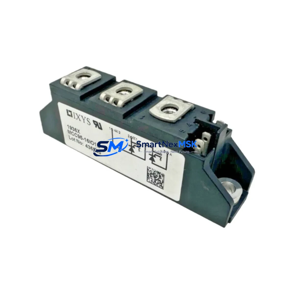
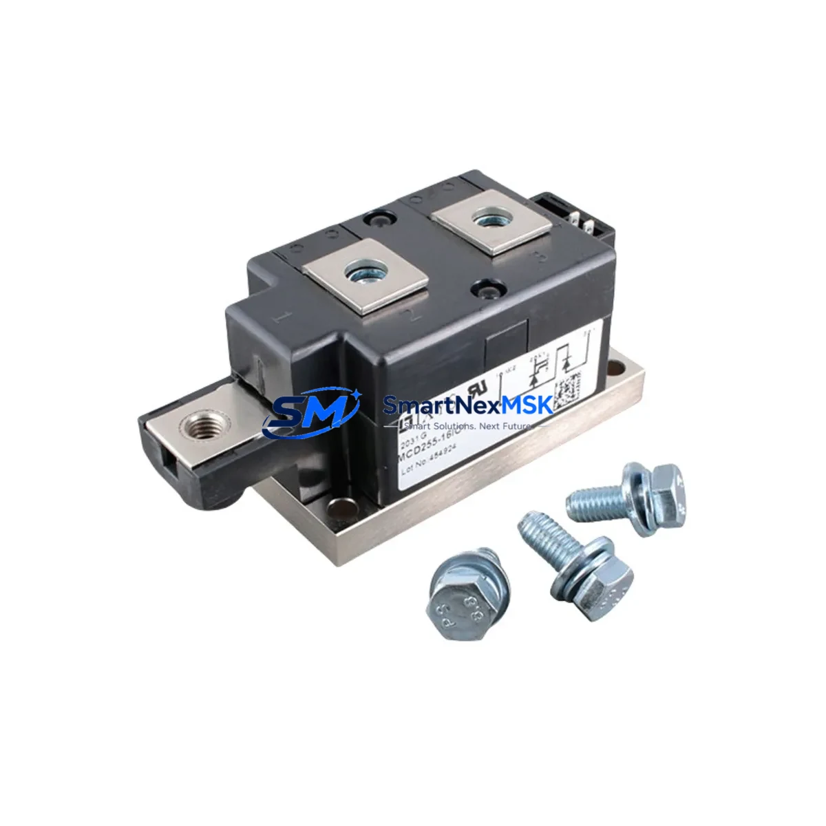
The IXYS MCD255-16I01 is a 1600V, 255A thyristor diode module engineered for demanding industrial power conversion and motor drive applications. As a retrofit-ready replacement for legacy MCD series configurations, this module delivers verified electrical compatibility, robust thermal performance, and a direct mechanical fit for existing control cabinet installations. Whether you are modernizing a discontinued drive system, restoring a legacy rectifier bridge, or upgrading a phase-controlled power supply, the MCD255-16I01 provides a reliable, cost-effective path forward without requiring full system redesign.
Industrial facilities operating older IXYS MCD series thyristor stacks frequently encounter obsolescence challenges when original modules reach end-of-life. The MCD255-16I01 addresses this directly: its standard 34mm isolated base package, M6 power terminal studs, and gate-cathode pin layout are dimensionally compatible with the mounting footprints used across the MCD series product family. Before installation, engineers should verify the existing heatsink thermal resistance, confirm gate trigger current requirements against the firing board output, and inspect the snubber circuit values to ensure they remain within the module’s dV/dt rating.
Upgrade Compatibility Table
| Parameter | MCD255-16I01 Specification | Retrofit Notes |
|---|---|---|
| Repetitive Peak Voltage (VRRM) | 1600V | Confirm line voltage and surge margin of existing system |
| Average On-State Current (IT(AV)) | 255A | Verify heatsink capacity and airflow; derate per application |
| Package / Mounting | 34mm isolated base, M6 studs | Direct fit for standard MCD series heatsink assemblies |
| Gate Trigger Current (IGT) | ≤150mA (typ.) | Verify firing board pulse amplitude; adjust if required |
| Thermal Resistance (Rth j-c) | ≤0.10 K/W | Re-apply thermal compound; inspect heatsink surface flatness |
| Communication / Control Interface | Gate pulse (analog firing board) | Compatible with existing SCR firing boards; no protocol change |
| Replacement Recommendation | Direct drop-in for MCD255 series | Cross-reference MCD255-14I01 (1400V) for lower-voltage lines |
| Commissioning Focus | Gate waveform, thermal runaway check | Monitor junction temperature during first load cycle |
| Warranty | 12 Months | Covers manufacturing defects; full pre-shipment functional test |
Retrofit Planning for Existing Automation Systems
A successful MCD255-16I01 retrofit begins well before the module arrives on site. Start by documenting the existing power stack configuration: identify whether the system uses a three-phase fully controlled bridge (six thyristors) or a semi-controlled bridge (three thyristors and three diodes), and confirm the total current demand against the 255A rating. In many legacy motor drive cabinets, the MCD255-16I01 operates alongside an IXYS MDD255-16N1 fast recovery diode module in the freewheeling position — both share the same package footprint, simplifying simultaneous replacement during a planned maintenance window.
Power supply integrity is the next checkpoint. Confirm that the existing DC bus capacitor bank, typically a series of electrolytic capacitors rated for the DC link voltage, remains within its rated capacitance and ESR values. Aging capacitors in legacy rectifier systems are a common cause of premature thyristor failure after module replacement. Similarly, inspect the AC line reactor or input transformer for signs of insulation degradation, as these components directly affect the dV/dt stress seen by the new module.
Terminal wiring adaptation is straightforward for most MCD series installations. The M6 anode and cathode studs accept standard copper bus bars or ring-lug cables used in the original assembly. Torque all power connections to the manufacturer’s specification — typically 6–8 Nm for M6 studs — to prevent contact resistance heating. The gate and cathode signal leads should be routed away from high-current conductors to minimize noise pickup on the firing pulse.
For systems using a dedicated SCR firing board — such as those found in older Eurotherm, Siemens, or ABB DC drive platforms — verify that the firing board’s pulse transformer output is correctly matched to the MCD255-16I01 gate characteristics. In some legacy installations, the firing board also interfaces with an IXYS VUO series three-phase bridge rectifier module for auxiliary power; this module should be inspected and replaced if it shows signs of thermal stress or leakage current drift.
Where the control system includes a programmable logic controller managing the firing angle reference, confirm that the analog output signal range (typically 0–10V or 4–20mA) remains within the firing board’s input specification. No firmware changes are required for a like-for-like thyristor module swap, but it is good practice to back up the PLC program and HMI screen configuration before beginning any power cabinet work. If the system uses a PROFIBUS or Modbus RTU link between the drive controller and a supervisory SCADA system, verify that the communication link remains active throughout the retrofit by keeping the control power energized while the main power is isolated.
Downtime Control During System Migration
Minimizing production downtime during a thyristor module replacement requires a structured approach. Begin by scheduling the replacement during a planned maintenance window and preparing all materials in advance: the MCD255-16I01 module, thermal interface compound, calibrated torque wrench, gate pulse tester, and a clamp-on ammeter for post-installation load verification.
Isolate and lock out the main AC supply before opening the control cabinet. Discharge the DC bus capacitors fully — use a resistive discharge tool and verify with a calibrated voltmeter before touching any bus bar. Remove the failed module by unbolting the power studs and disconnecting the gate-cathode leads, noting the original wiring orientation with photographs or labels.
Install the MCD255-16I01 with fresh thermal compound applied evenly to the base. Reconnect all power and signal terminals, torque to specification, and perform a gate continuity check before re-energizing. On first power-up, bring the system up under reduced load — approximately 25% of rated current — and monitor the module’s heatsink temperature for the first 15 minutes. Confirm that the firing angle responds correctly to the control reference and that the DC output voltage is within the expected range. This staged commissioning approach protects the original PLC program logic and HMI display configuration from any transient disturbances during the restart sequence, maintaining control system continuity throughout the migration.
Pre-shipment testing of every MCD255-16I01 unit includes forward voltage drop measurement, gate trigger verification, and high-potential isolation testing. Each module ships with a test report and is covered by a 12-month warranty against manufacturing defects.
Retrofit Support FAQ
Q: Is the MCD255-16I01 a direct replacement for the MCD255-16I01B or other MCD255 suffix variants?
A: The MCD255-16I01 is electrically and mechanically compatible with most MCD255 suffix variants sharing the same 1600V voltage class and 34mm package. Minor differences in gate sensitivity between suffix variants are within the tolerance range of standard SCR firing boards. We recommend confirming the gate trigger current specification against your firing board datasheet before installation.
Q: What wiring changes are needed when replacing a failed MCD255 module?
A: In most cases, no wiring changes are required. The M6 power studs and gate-cathode pin positions are identical to the original MCD series layout. Re-use existing bus bars and signal cables after inspecting them for insulation damage. Apply fresh thermal compound to the heatsink interface and torque all connections to specification.
Q: How do I verify compatibility before ordering?
A: Provide your existing module part number, system voltage, and rated load current. Our technical team will cross-reference the specifications and confirm suitability. We also accept requests for pre-shipment functional testing with customer-specified gate pulse parameters.
Q: What does the 12-month warranty cover?
A: The warranty covers manufacturing defects in materials and workmanship for 12 months from the date of shipment. Each unit undergoes pre-shipment electrical testing including gate trigger, forward voltage, and isolation verification. Warranty claims are processed with a replacement unit dispatched upon receipt and inspection of the returned module.
© 2026 SMARTNEXMSK. All rights reserved.
Original Source: https://smartnexmsk.com
Contact: sales@smartnexmsk.com | +86 18259474341